
Connector filler element insertion tool and method

Inactive Publication Date: 2006-02-16
THE BOEING CO
View PDF17 Cites 2 Cited by
  • Summary
  • Abstract
  • Description
  • Claims
  • Application Information

AI Technical Summary

Benefits of technology

[0010] The foregoing needs are met, to a great extent, by the present invention. Various embodiments of the present invention provide an improved device for installing filler elements into the electrical connectors, provide an improved tool for the installation of filler rods without damaging the electrical connectors, and / or provide an improved device for installing filler elements of varying sizes to accommodate variously sized electrical connectors as desired.
[0011] In one aspect, an apparatus is provided that in some embodiments has a hollow metal tube, with one end inserted in a wooden handle, the other open to receive a sealing plug. It is to be used as an insertion guide to install filler rods or elements (i.e., sealing plugs) into electrical connectors. This provides a method and apparatus that is ergonomic in form and durable and safe to use when inserting sealing plugs into electrical connectors.

Problems solved by technology

For example, the tool is somewhat hard to use and often requires the use of alcohol for lubrication.
The plastic tool also can sometimes break easily.
Other existing tools also are susceptible to breakage and can cause damage.
These existing tools are also somewhat slow to use because they are not user-friendly or ergonomic to hold.
The potential of damage to electrical connectors is of concern because the connectors can be very expensive.
If damage does occur, then significant downtime may result.

Method used


Image

  • Connector filler element insertion tool and method
  • Connector filler element insertion tool and method
  • Connector filler element insertion tool and method

Examples


Embodiment Construction

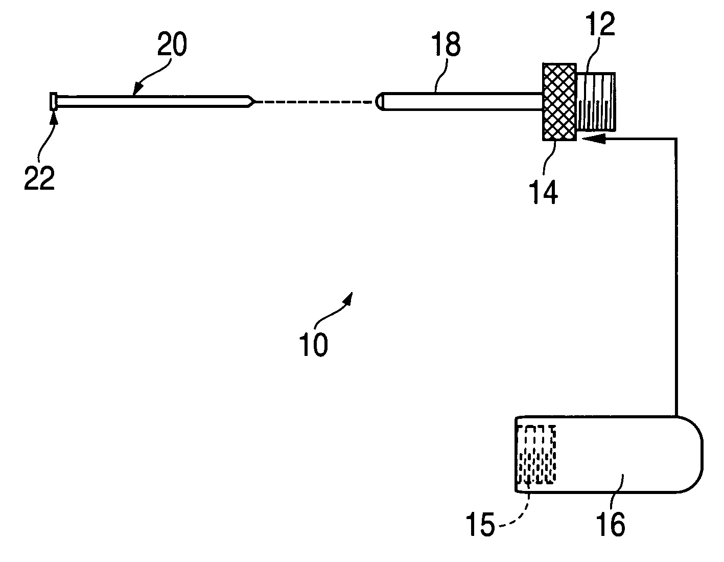
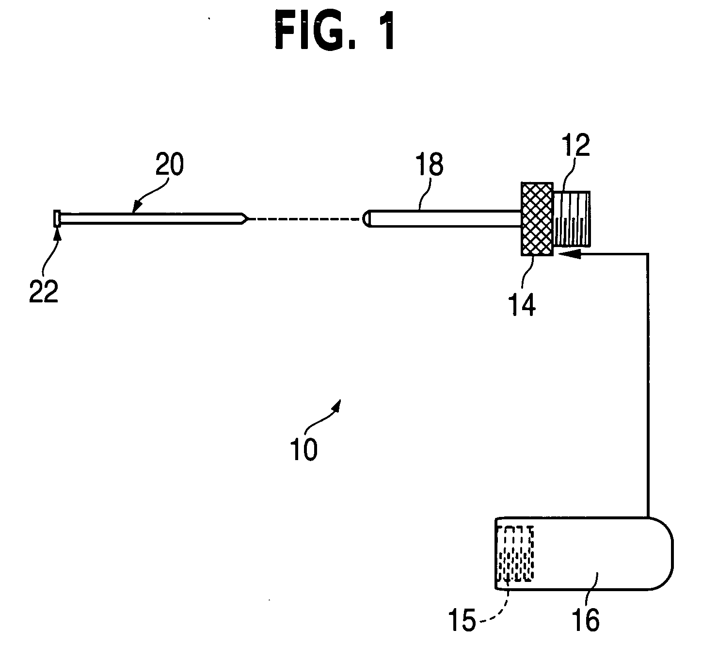
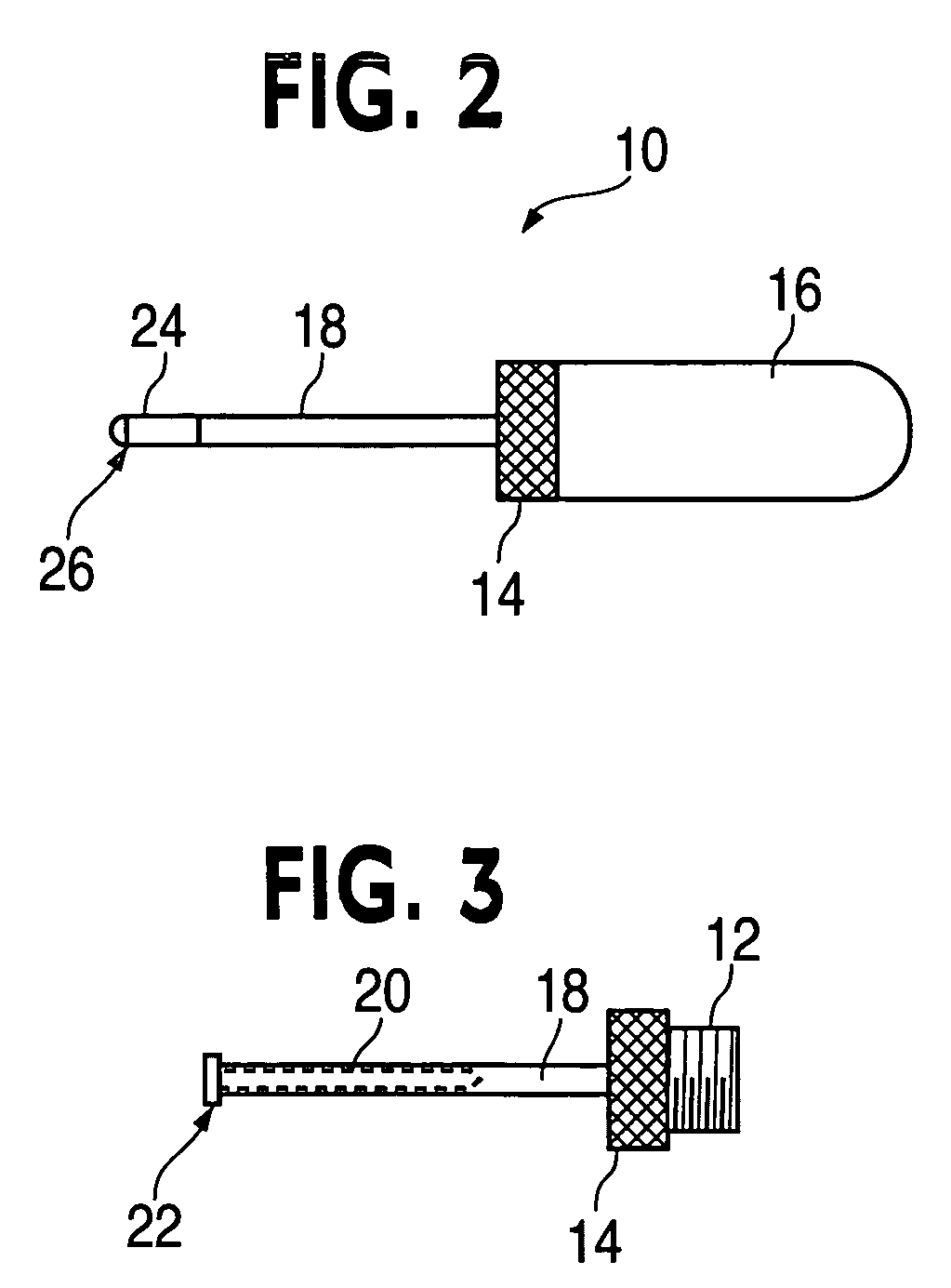
[0026] The invention will now be described with reference to the drawing figures, in which like reference numerals refer to like parts throughout. Referring to FIGS. 1 and 2, an embodiment in accordance with the present invention provides an insertion tool 10 used to insert filler elements 20 (preferably made of plastic) into the unused cavities or holes of a grommet 40 in an electrical connector 42 otherwise occupied by a pin or socket as shown in FIGS. 8-10. These filler elements 20 are called “filler rods” or “sealing plugs” and the insertion tool 10 used to insert them is different than the tool used to insert (or remove) a pin / socket.

[0027] Referring to FIG. 2, the present invention includes a hollow tube 18 attached to an ergonomic handle 16. Preferably, the hollow tube 18 is made of steel. The hollow tube 18 may be connected or integral to a threaded connector 12 having a serrated grip 14. The threaded connector 12 may be screwed into the threaded portion 15 of ergonomic han...


PUM

PropertyMeasurementUnit
Lengthaaaaaaaaaa
Sizeaaaaaaaaaa

Abstract

An apparatus for inserting filler elements such as sealing plugs within electrical connectors includes a threaded connector, a serrated grip, an ergonomic handle and a hollow tube for receiving filler elements of various sizes. The hollow tube assembly may be interchangeable with variously sized hollow tubes to accommodate the various sized filler elements.

Description

FIELD OF THE INVENTION [0001] The present invention relates generally to electrical connectors. More particularly, the present invention relates a tool for inserting sealing plugs into electrical connectors. BACKGROUND OF THE INVENTION [0002] Bundles of wires carrying multiple signals are usually connected to other similar bundles or interfaced to devices such as instruments and control mechanisms through the use of electrical connectors into which contacts corresponding to the individual wires of the bundles are assembled. The connectors allow leads from the wires to be brought into an orderly mating relationship with conductive leads from other wire bundles, instruments, or control mechanisms. [0003] It is conventional for a connector to comprise a pair of cylindrical shells which are adapted for fitting together in a single prescribed manner. Each such shell includes a contact receiving insert. Each insert is made of a dielectric material and is in the form of a plate having an i...

Claims


Application Information

Patent Timeline
IPC IPC(8): H01R43/20
CPCH01R13/443H01R13/52Y10T29/53209Y10T29/49208H01R43/20
Inventor JOHNSON, GERALD M.
Owner THE BOEING CO
Learn More