Device for welding plastic

a technology of plastic welding and nozzles, which is applied in the direction of welding/soldering/cutting articles, other domestic objects, manufacturing tools, etc., can solve the problems of affecting the quality and ultimately strength of welds, nozzles that deliver the focused stream of heated air are often overheated, and handheld applicators are susceptible to damage, etc., to achieve strong and reliable welds, durable and safe to use, and low cost of manufactur

Inactive Publication Date: 2018-04-05
LEWIS TIMOTHY C
View PDF3 Cites 3 Cited by
  • Summary
  • Abstract
  • Description
  • Claims
  • Application Information

AI Technical Summary

Benefits of technology

[0010]It is another object of the present invention to provide a welding device as described above that designed to produce a strong and reliable weld.
[0011]It is yet another object of the present invention to provide a welding device as described above that is durable and safe to use.
[0012]It is still another object of the present invention to provide a welding device as described above that has a limited number of parts, is inexpensive to manufacture, and is easy to use.

Problems solved by technology

However, the present inventor has recognized that the presence of oxygen in the supply of heated air compromises the quality and ultimately the strength of the weld.
In particular, it has been found that the nozzle that delivers the focused stream of heated air often overheats due to a lack of sufficient cooling means.
As a result, the handheld applicator is rendered susceptible to damage or, even on occasion, melting after prolonged use.
Namely, traditional plastic welders are not typically equipped with means to monitor and regulate the temperature of certain components (e.g., the nozzle) over time.
As a result, if inadequately monitored by the user, the device could pose a significant fire hazard.

Method used


Image

  • Device for welding plastic
  • Device for welding plastic
  • Device for welding plastic

Examples


Embodiment Construction

Welding Device 11

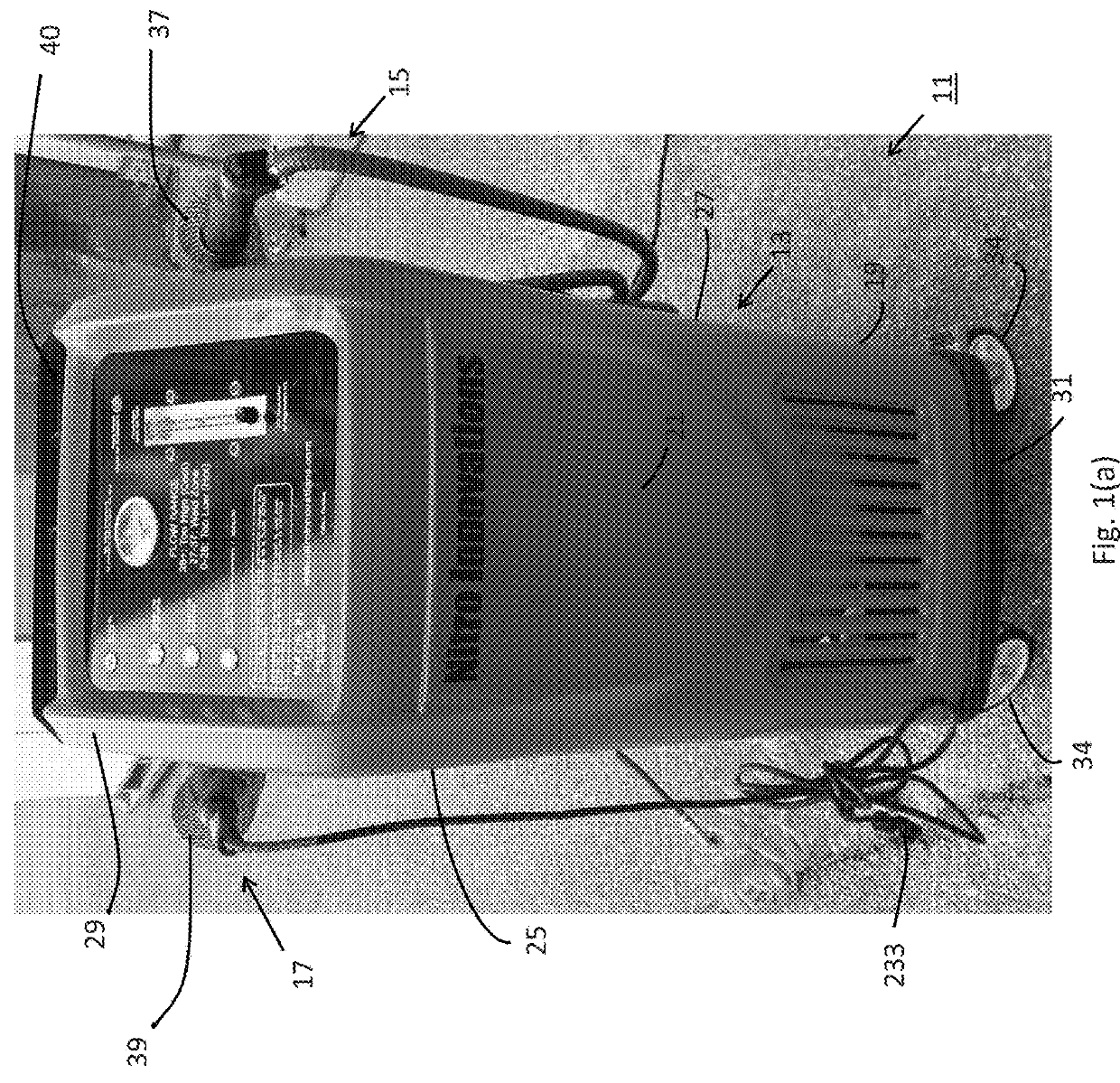
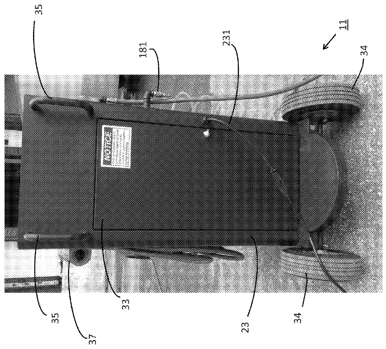
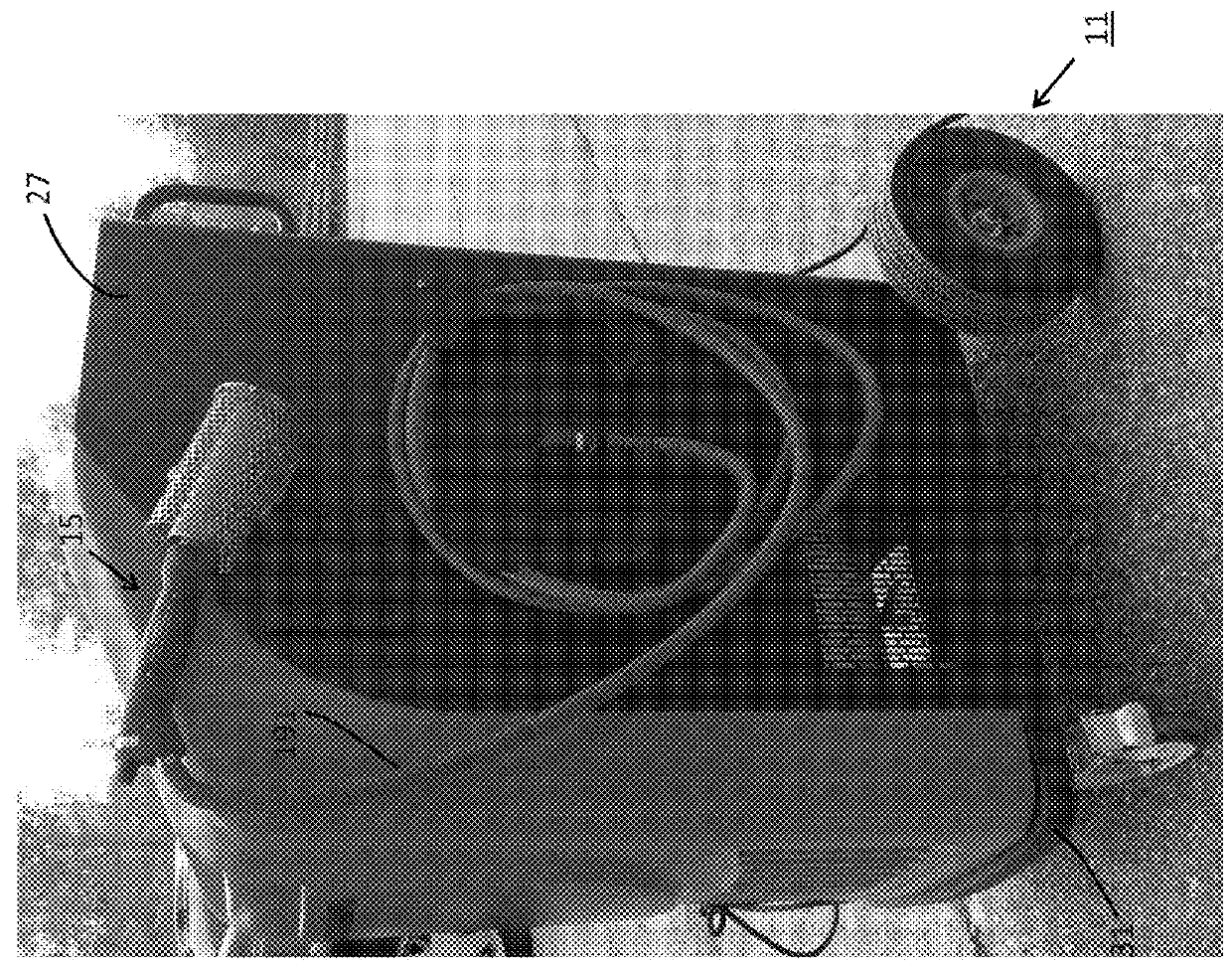
[0021]Referring now to FIGS. 1(a)-(c), there are shown front perspective, rear perspective, and right side perspective views, respectively, of a welding device constructed according to the teachings of the present invention, the welding device being identified generally by reference numeral 11. As will be described in detail below, welding device 11 is specifically designed to yield a high-quality and durable weld in a safe and reliable fashion.

[0022]Welding device 11 is designed primarily for use in the welding together of plastic materials of similar compositions. Most notably, device 11 is particularly well-suited for use in repairing cracked, torn or otherwise damaged automotive bumpers, which are traditionally constructed of polypropylene or other similar thermoplastic material. However, it should be noted that device 11 is not limited for use in the welding of specific materials in any particular application. Rather, it is to be understood that device 11 could...


PUM

PropertyMeasurementUnit
air pressureaaaaaaaaaa
pressureaaaaaaaaaa

Abstract

A device for welding plastic materials includes a handheld, wand-type applicator that dispenses a focused stream of oxygen-free air for optimum fusion. The applicator comprises a heating coil that warms the dispensed air to a sufficient temperature to sufficiently meld the plastic materials. A weld air delivery system delivers the supply of oxygen-free air to the weld applicator. A separate coolant air delivery system includes a tank that collects a reserve supply of ambient air that is used to cool the heating coil when applicator is not actively welding plastic materials. The inclusion of separate delivery systems ensures that ambient air is used to cool applicator, whereas oxygen-free air is preserved for use in welding applications. For safety purposes, a switch deactivates the heating coil when the pressure of the reserve air in the tank falls beneath a predefined threshold that is considered necessary to adequately cool the applicator.

Description

FIELD OF THE INVENTION[0001]The present invention relates generally to welding devices and, more particularly, to devices designed principally for use in the welding of plastic materials.BACKGROUND OF THE INVENTION[0002]Welding devices are well known in the art and are commonly used to join together certain items. Specifically, through the application of focused heat and / or pressure, materials of similar compositions can be fused together and, if necessary, reshaped to form a unitary item.[0003]A plastic welder, or plastic welding tool, is one type of welding device that is designed primarily for use in the welding of plastic materials. Plastic welders typically include a handheld applicator, or nozzle, that delivers a focused stream of heated air. In use, a strip of filler material is often aligned between a multiple pieces of plastic of a similar composition. By applying a focused stream of heated air at the juncture, or joint, of the separate materials, the various plastic pieces...

Claims


Application Information

Patent Timeline
Patent Type & Authority Applications(United States)
IPC IPC(8): B29C65/00B29C65/10
CPCB29C66/865B29C65/10B23K2203/42B29L2031/3044B29C65/12B29C66/00141B29C66/71B29C66/73921B29C66/8181B29C66/861B29C66/8652B29C66/9672B29C66/9674B29C73/34B23K2103/42B29K2023/12
Inventor LEWIS, TIMOTHY C.
Owner LEWIS TIMOTHY C
Why Eureka
Try Eureka