
Polishing slurry, method of producing same, and method of polishing substrate

a technology of slurry and substrate, which is applied in the direction of lanthanide oxide/hydroxide, manufacturing tools, other chemical processes, etc., can solve the problems of reducing the removal speed of oxide layer, and reducing the removal speed of nitride layer, so as to reduce the number of micro-scratches

Inactive Publication Date: 2006-02-16
K C TECH +1
View PDF15 Cites 11 Cited by
  • Summary
  • Abstract
  • Description
  • Claims
  • Application Information

AI Technical Summary

Benefits of technology

[0012] Accordingly, the present invention has been made keeping in mind the above problems occurring in the prior art, and an object of the present invention is to provide a high performance nano ceria slurry which is capable of being applied in a process of producing ultra highly integrated semiconductors of 0.13 μm or less, particularly, an STI process, and is capable of minimizing micro-scratches that are fatal to semiconductor devices by properly employing a method and a device for pre-treating various particles, a dispersing device and a method of operating the dispersing device, a method of adding a chemical additive and an amount added, and a device for transferring samples.
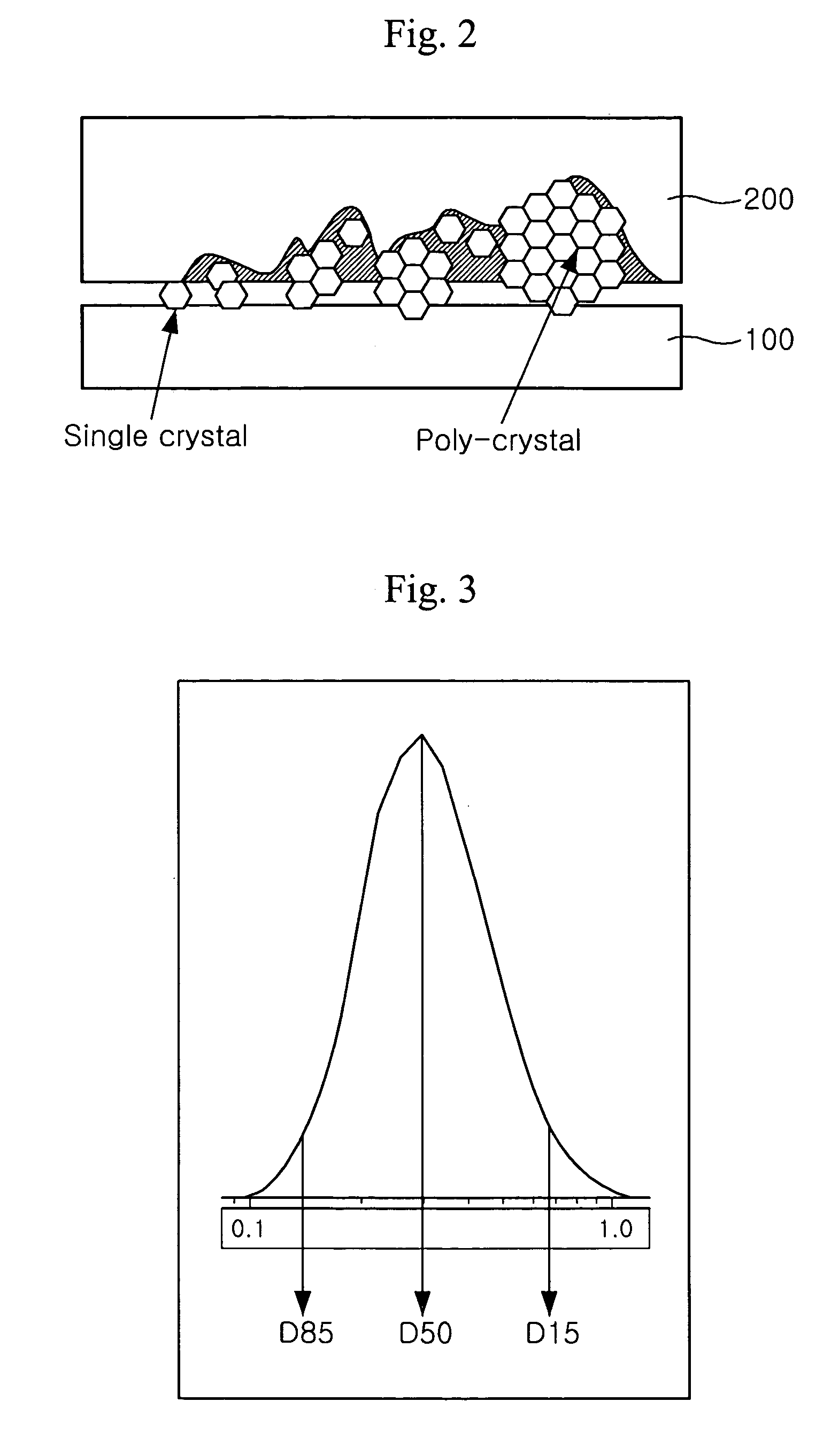
[0015] Based on the above description, the present invention aims to provide a slurry that is capable of minimizing micro-scratches and maintaining a suitable removal rate and in which dispersion is stabilized.
[0016] Another object of the present invention is to provide a method of effectively polishing a semiconductor substrate having a fine design rule using the above slurry.
[0017] In order to accomplish the above objects, the present invention provides a polishing slurry which comprises polishing particles in which a surface area per unit weight is changed so as to minimize agglomeration of the polishing particles and improve dispersion stability.

Problems solved by technology

However, the use of the additive is disadvantageous in that the removal speed of the oxide layer, as well as the removal speed of the nitride layer, is reduced.
Furthermore, the polishing agent of the ceria slurry typically has particles larger than those of the silica slurry, and therefore scratches the surface of the wafer.
However, if polishing speed selectivity of the oxide layer to the nitride layer is low, a dishing phenomenon, in which an excessive volume of the oxide layer is removed, occurs due to the loss of adjacent nitride layer patterns.
Thus, it is impossible to achieve uniform surface flattening.
However, the above prior arts disclose only the average particle size of the polishing particles constituting the polishing slurry and the range thereof, but lack details on how to disperse the particles.

Method used


Image

  • Polishing slurry, method of producing same, and method of polishing substrate
  • Polishing slurry, method of producing same, and method of polishing substrate
  • Polishing slurry, method of producing same, and method of polishing substrate

Examples


Embodiment Construction

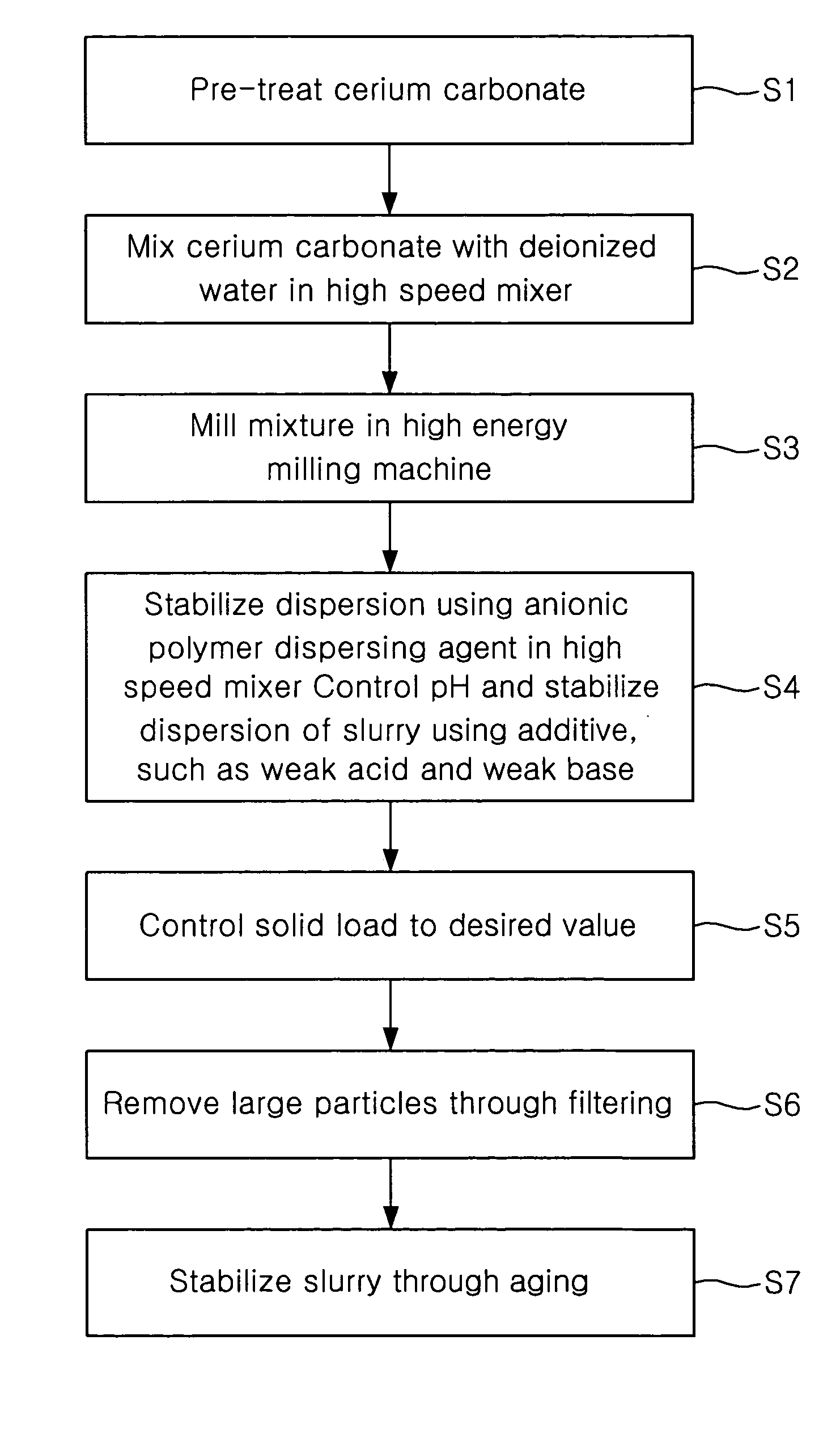
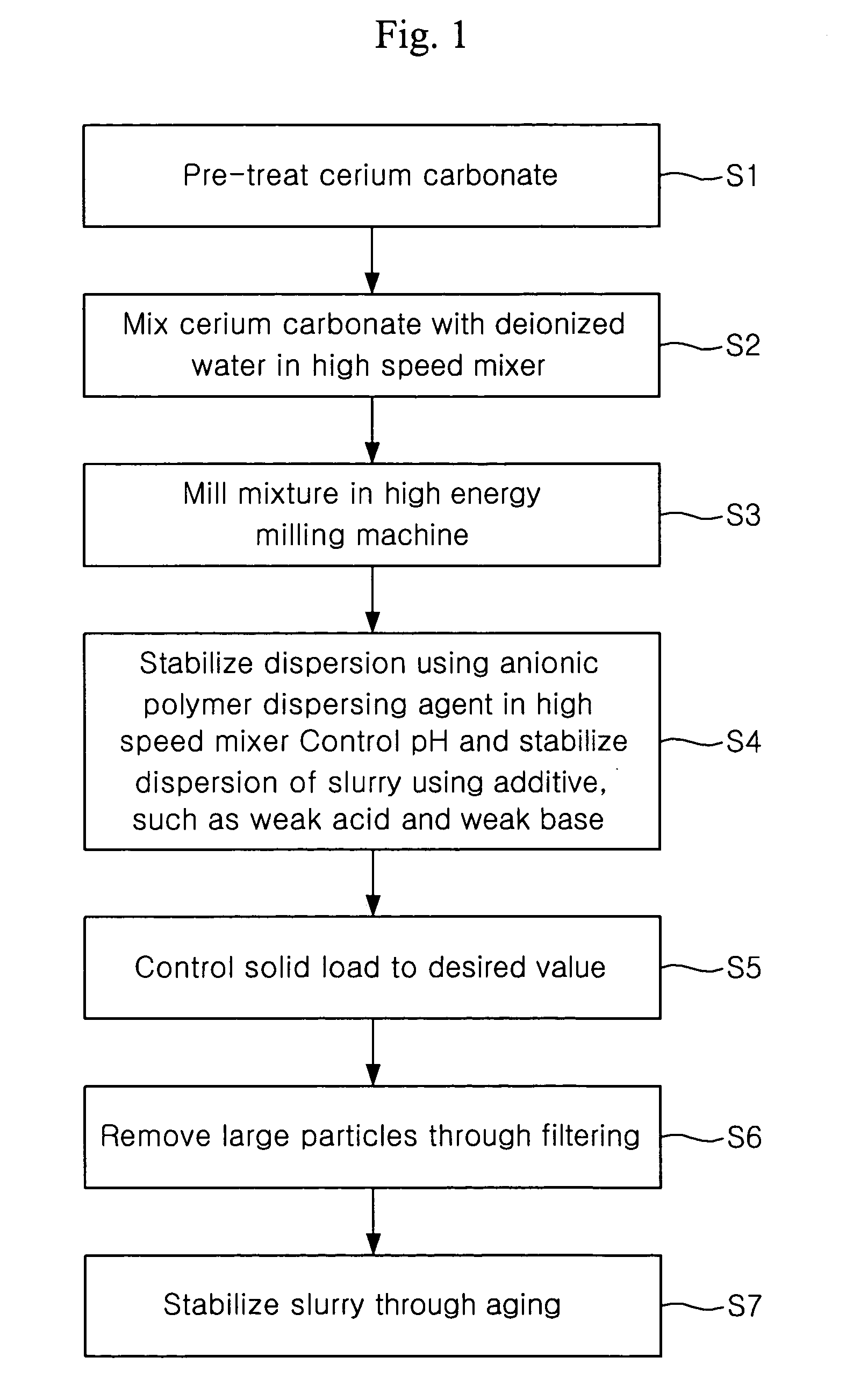
[0041] Hereinafter, a process of producing a polishing slurry according to the present invention and a characteristic analysis of the polishing slurry will be separately described in detail. Furthermore, a description will be given of a method of producing the polishing slurry using ceria as a polishing agent, deionized water as a dispersion medium thereof, and an anionic polymer dispersing agent as a dispersing agent. Additionally, a description will be given of the CMP results, such as an oxide film polishing speed and selectivity, depending on process conditions. Many modifications and variations of the present invention, which will be described later, are possible, and the scope of the present invention is not limited by the following description.

[0042] [Production of Ceria Slurry]

[0043] The ceria slurry of the present invention is produced so as to contain ceria powder, deionized (DI) water, anionic polymer dispersing agent, and an additive such as a weak acid or weak base. A ...


PUM


Abstract

Disclosed is a polishing slurry, particularly, a slurry for chemical mechanical polishing, which is used in a chemical mechanical polishing process for flattening a semiconductor laminate. More particularly, the present invention provides a method of producing a slurry which has high removal selectivity to a nitride layer used as a barrier film in a shallow trench isolation CMP process needed to fabricate ultra highly integrated semiconductors of 256 mega D-RAM or more (Design rule of 0.13 μm or less) and which decreases the occurrence of scratches on a flattened surface, and a method of polishing a substrate using the same.

Description

BACKGROUND OF THE INVENTION [0001] This application claims the priority of Korean Patent Application No. 2004-0059245, filed on Jul. 28, 2004, 2004-0059246, filed on Jul. 28, 2004, 2004-0067536, filed on Aug. 26, 2004 and 2004-0118158, filed on Dec. 31, 2004 in the Korean Intellectual Property Office, the disclosure of which is incorporated herein in its entirety by reference. [0002] 1. Field of the Invention [0003] The present invention relates to a polishing slurry, particularly, a slurry for chemical mechanical polishing (hereinafter, referred to as ‘CMP’), which is used in a chemical mechanical polishing process for flattening a semiconductor laminate. More particularly, the present invention pertains to a method of producing a slurry which has high removal selectivity to a nitride layer used as a barrier film in a shallow trench isolation CMP process needed to fabricate ultra highly integrated semiconductors of 256 mega D-RAM or more (Design rule of 0.13 μm or less) and which d...

Claims


Application Information

Patent Timeline
IPC IPC(8): C09K3/14B24D3/02C09C1/68C01F17/235
CPCB82Y30/00C01F17/0043C01P2004/52C09K3/1463C01P2006/12C01P2006/22C09G1/02C01P2004/64C01F17/235
Inventor KIM, DAE HYEONGHONG, SEOK MINJEON, JAE HYUNPAIK, UN GYUPARK, JEA GUNKIM, YONG KUK
Owner K C TECH
Learn More