Bidirectional coupling device with variable transmission characteristics

a technology of transmission characteristics and coupling devices, which is applied in the direction of motor/generator/converter stoppers, gearing, dynamo-electric converter control, etc., can solve the problem that the single performance of both types of couplers of the prior art as described above is usually subject to limited application

Active Publication Date: 2006-02-16
YANG TAI HER
View PDF4 Cites 8 Cited by
  • Summary
  • Abstract
  • Description
  • Claims
  • Application Information

AI Technical Summary

Problems solved by technology

The single performance of both types of the couplers of the prior art as described above is usually subject to limited application.

Method used


Image

  • Bidirectional coupling device with variable transmission characteristics
  • Bidirectional coupling device with variable transmission characteristics
  • Bidirectional coupling device with variable transmission characteristics

Examples


Embodiment Construction

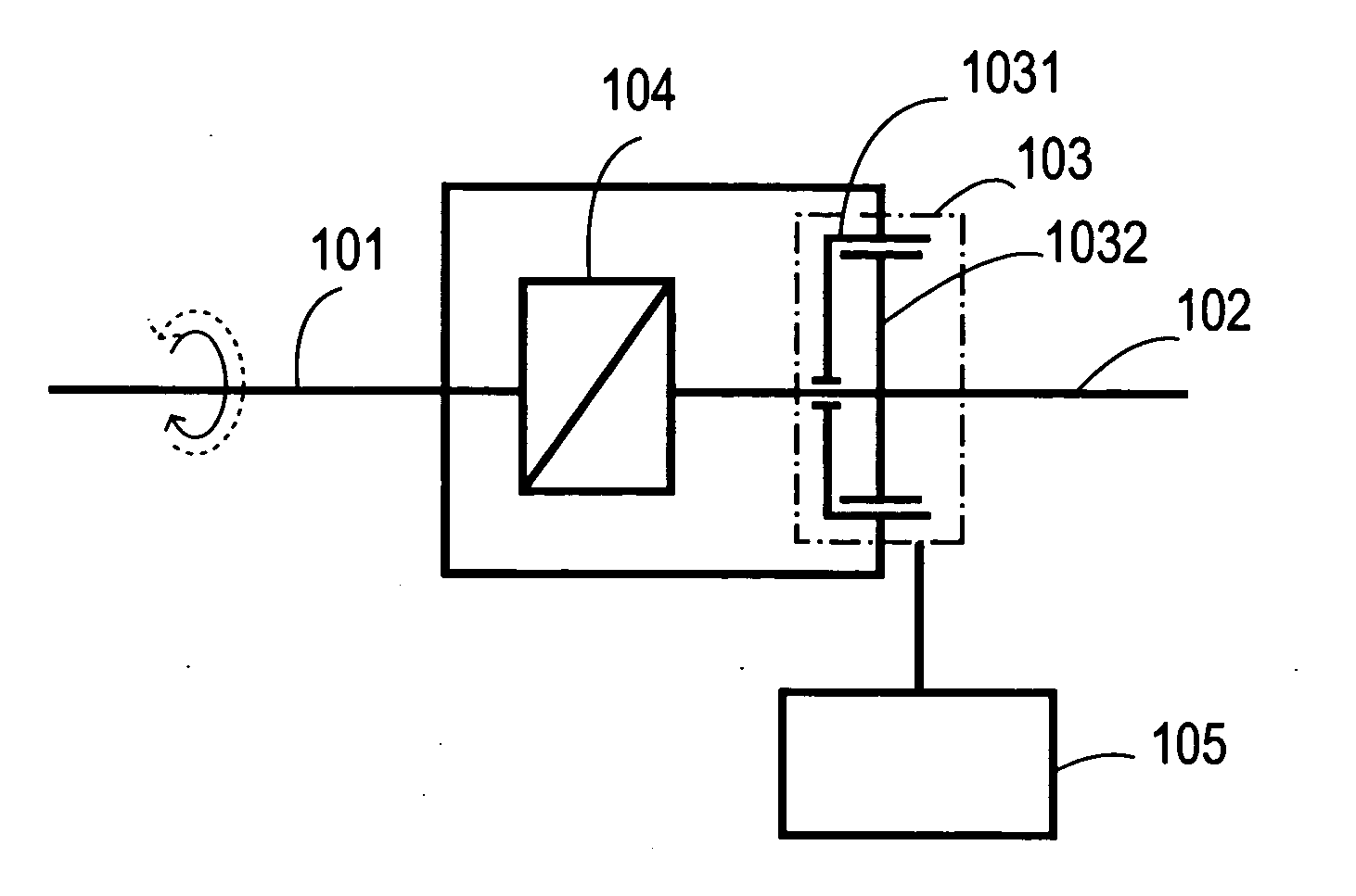
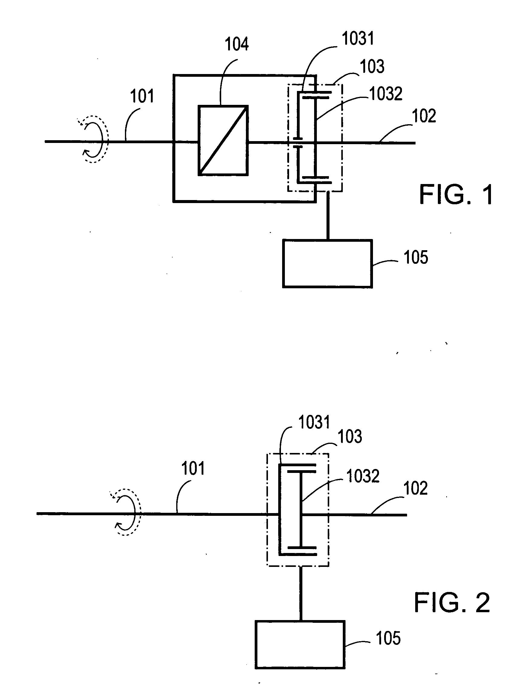
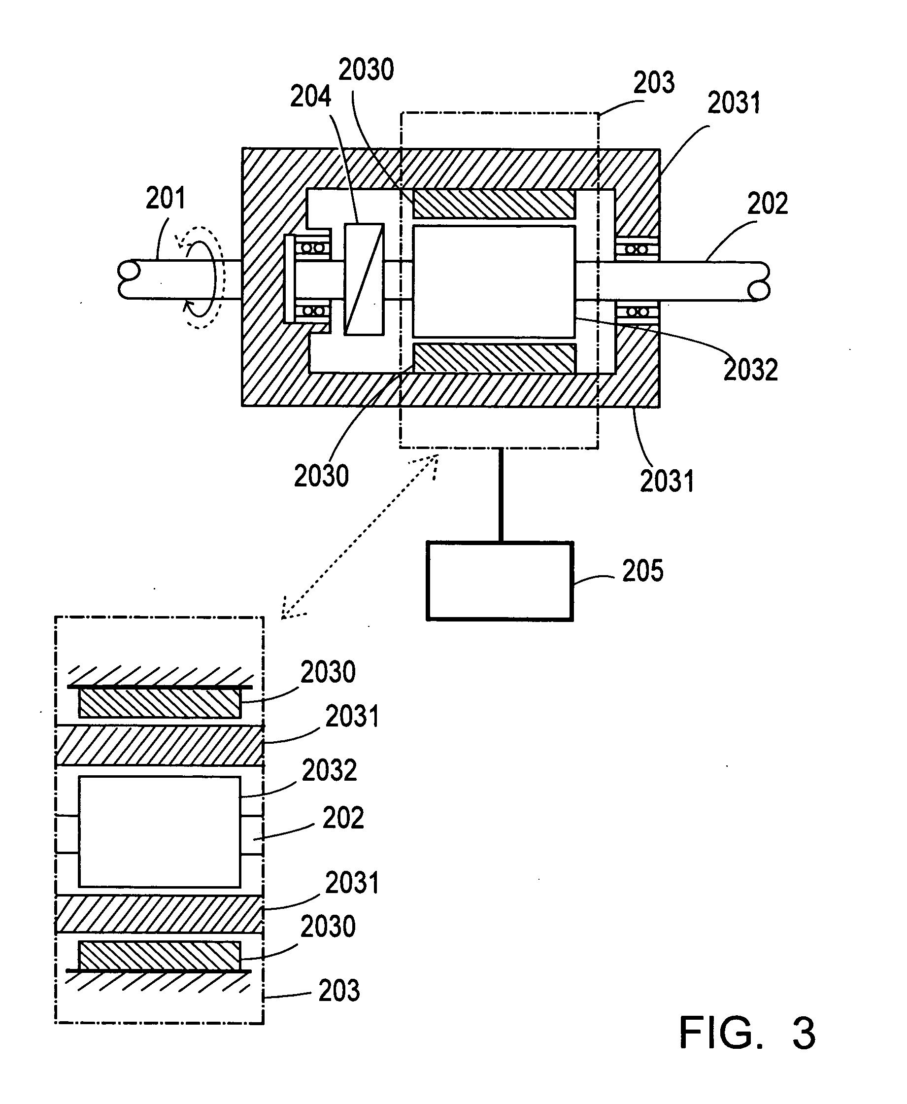
[0047] The present invention is related to a bidirectional-coupling device of revolution kinetics comprised of one or multiple first input / output end and one or multiple second input / output end. Wherein, when the revolution kinetics is transmitted from the first input / output end, the present invention may execute continuous revolution difference as the load varies to indicate non-rigid revolution transmission characterized by delivering the accelerating kinetics with a specific or controllable flexibility or torque value; or inversely when the second input / output end feeds the transmission of revolution kinetics back to the first input / output end, the present invention may execute continuous revolution difference as the load varies for the non-rigid revolution transmission with a specific or controllable flexibility or torque value, or as elected, the present invention may execute rigid feedback transmission of revolution kinetics without the revolution difference.

[0048] Given with...


PUM


Abstract

A bidirectional flexible coupling device with variable transmission characteristics including one or multiple first input/out end and one or multiple second input/out end, indicating the transmission of specific or controllable flexibility or torque value when the first input/output end drives the second input/output end for transmission; and according to operation requirements, the transmission may be of specific or controllable flexibility or torque value or of rigid without revolution difference when the second input/output end drives the first input/output end.

Description

BACKGROUND OF THE INVENTION [0001] (a) Field of the Invention [0002] The present invention is related to a bidirectional coupling device with variable transmission characteristics, and more particularly, to one capable of functioning as a mechanism of bidirectional revolution transmission kinetics. It is comprised of a coupler of bidirectional revolution transmission one or multiple first input / output end and one or more than one second input / output end; wherein, a continuous revolution difference can be exercised between both input / out ends when the second input / output end is driven by the first input / output end for transmission while indicating transmission characteristics that the flexibility or torque of the transmission may be of specific value or a controllable value. On the contrary, when the second input / output end drives the first input / output end for transmission, the coupler depending on the operation requirements may elect to execute continuous revolution difference with...

Claims


Application Information

Patent Timeline
Patent Type & Authority Applications(United States)
IPC IPC(8): F16H35/02
CPCF16D41/04Y10T74/19555H02K49/00F16D47/04
Inventor YANG, TAI-HER
Owner YANG TAI HER
Why Eureka
Try Eureka