Trigger switch structure of nail driver

Inactive Publication Date: 2006-02-16
BESCO PNEUMATIC CORP
View PDF13 Cites 4 Cited by
  • Summary
  • Abstract
  • Description
  • Claims
  • Application Information

AI Technical Summary

Benefits of technology

[0006] Accordingly, the primary object of the present invention is to provide a trigger switch structure of a nail driver, wherein by adjusting the position of the switch with respect to the position of the handle. The moving length of the trigger cover can be adjusted. The operation of the switch can be performed quickly. Thereby by the position of the switch, the triggering states of the nail driver body can be identified.

Problems solved by technology

The user must place the nail driver to a table or ground surface, otherwise it is difficult to perform the operation.
However, the operation is not a design of personality.
The structure of the prior art triggering switching device is very complicated and many small round cylinder elements are used, which is unbeneficial to the assembly work.
Thereby, the elements are easy to lose so as to affect the manufacturing speed and cost.
However, this is also a burden of the users.

Method used


Image

  • Trigger switch structure of nail driver
  • Trigger switch structure of nail driver
  • Trigger switch structure of nail driver

Examples


Embodiment Construction

[0018] In order that those skilled in the art can further understand the present invention, a description will be described in the following in details. However, these descriptions and the appended drawings are only used to cause those skilled in the art to understand the objects, features, and characteristics of the present invention, but not to be used to confine the scope and spirit of the present invention defined in the appended claims.

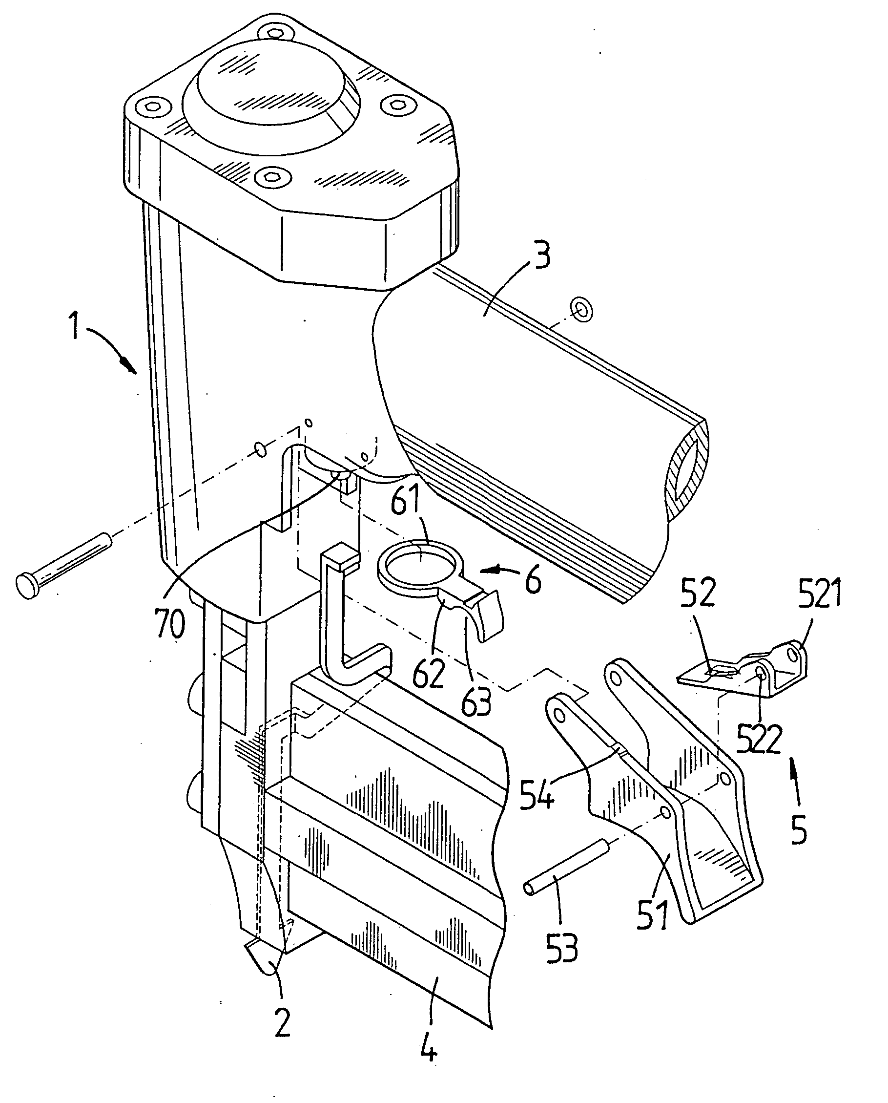
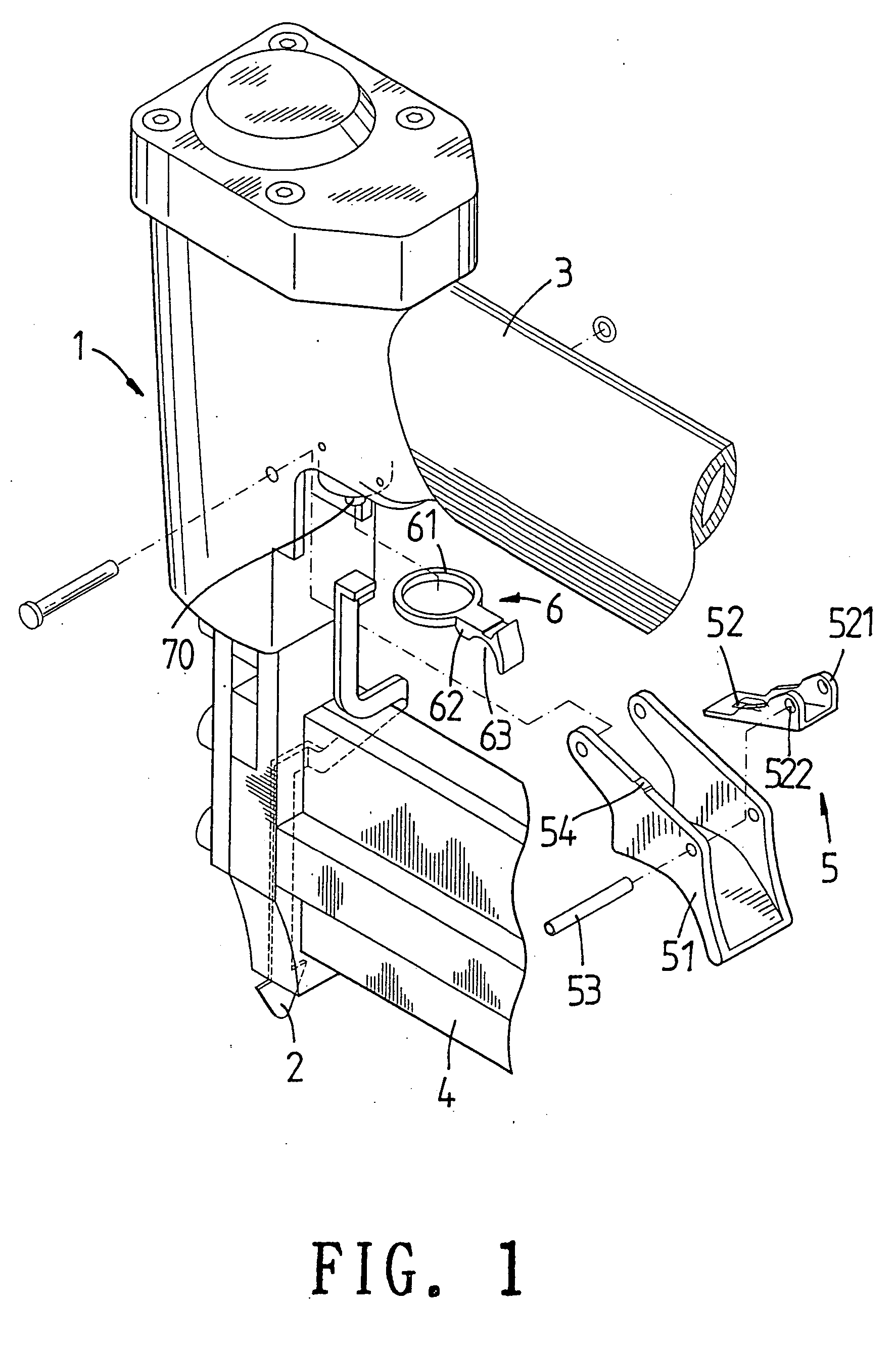
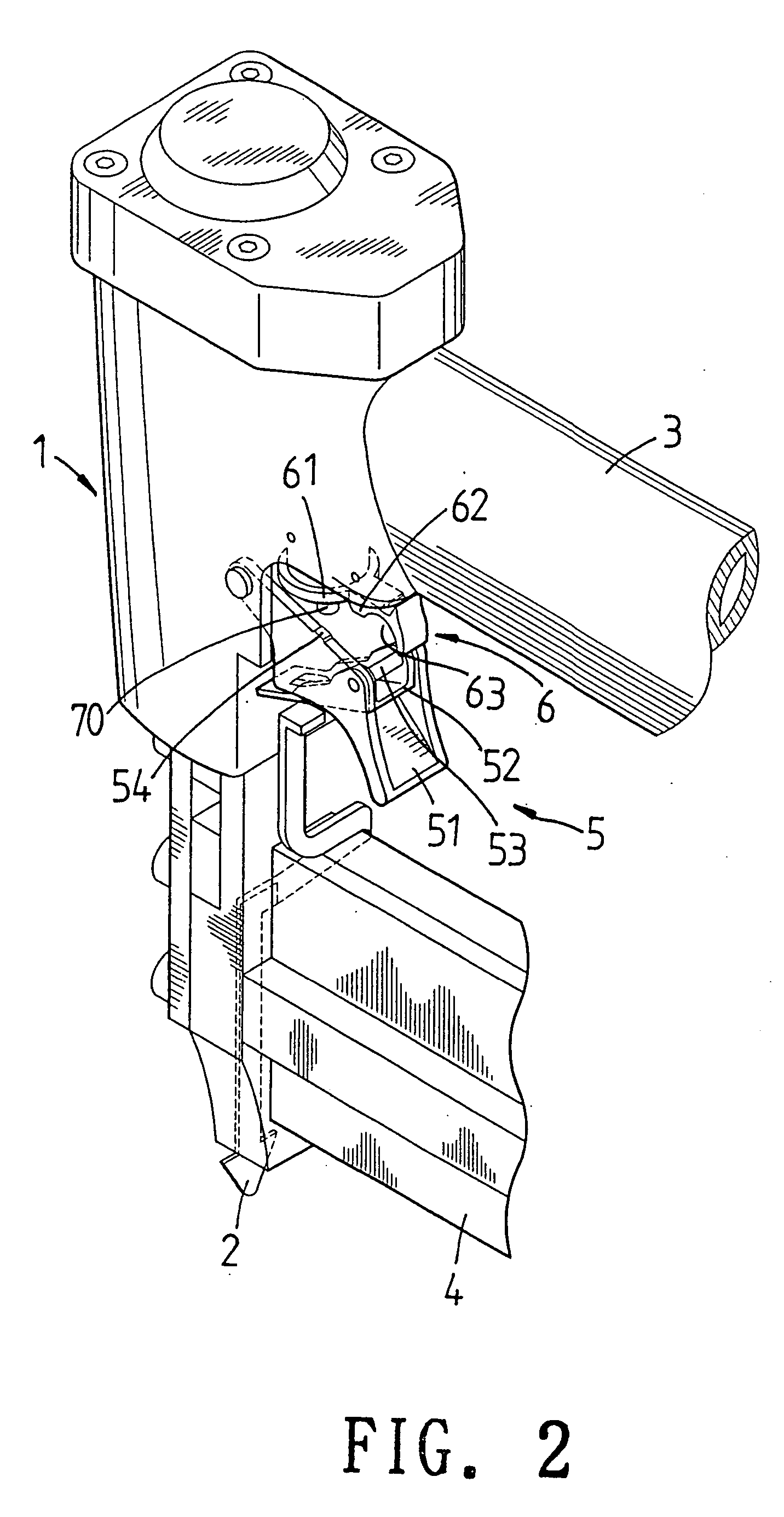
[0019] With reference to FIG. 1, the switching structure of a nail driver of the present invention is illustrated. The present invention includes a nail driver body 1, a security device 2, a handle 3, a nail cartridge 4, a trigger device 5, and a switch 6.

[0020] One end of the security device 2 is connected to the trigger device 5 of the nail driver body 1.

[0021] The trigger device 5 is formed by the following element:

[0022] A trigger cover 51 is pivotally installed to the nail driver body 1. The trigger device 5 is a U shape device.

[0023] A...


PUM


Abstract

A trigger switch structure of a nail driver is disclosed. The nail driver body comprises a nail driver body; a security device; one end of the security device being connected to the trigger device of the nail driver body; a trigger device: a trigger cover pivotally installed to the nail driver body; the trigger device being a U shape device; a driving sheet pivotally connected to the trigger cover and received in the trigger cover; a pivotal rod passing through the holes on the trigger cover and the driving sheet so as to fix the driving sheet to the trigger cover; and a switch; one end of the switch being formed with a ring; a stopper being extended downwards from the ring; a lower side of the stopper being formed with a recess; and the stopper protruded downwards between the ring and the recess being buckled to the block.

Description

FIELD OF THE INVENTION [0001] The present invention relates to nail drivers, and particularly to a trigger switch structure of a nail driver, wherein by adjusting the position of the switch with respect to the position of the handle. The moving length of the trigger cover can be adjusted. The operation of the switch can be performed quickly. Thereby by the position of the switch, the triggering states of the nail driver body can be identified. BACKGROUND OF THE INVENTION [0002] Referring to FIGS. 5 to 8, the prior art triggering switching device of a nail driver is illustrated. In switching the triggering mode of the prior art triggering switching device, a press end 91 aside the trigger 90 is pressed so that a rotation end 92 protrudes from another side for moving the rotation end 92. An eccentric shaft 920 above the rotation end 92 moves a trigger sheet 92 to move upwards or downwards for determining a first trigger portion 930 or a second triggering portion 931 to trigger a nail ...

Claims


Application Information

Patent Timeline
IPC IPC(8): B25C1/04
CPCB25C1/008
Inventor LIN, CHIEN-CHUAN
Owner BESCO PNEUMATIC CORP
Why Eureka
Try Eureka