Non-contact switch apparatus

A switching device, non-contact technology, applied in electronic switches, electrical components, pulse technology, etc., can solve the problems of inability to switch quickly, insensitive to changes, etc., to prevent insensitive resistance changes and rapid switching operations. Effect

Inactive Publication Date: 2008-12-24
ALPS ALPINE CO LTD
View PDF2 Cites 2 Cited by
  • Summary
  • Abstract
  • Description
  • Claims
  • Application Information

AI Technical Summary

Problems solved by technology

However, when such a GMR element is used in a switching device, there is a problem that the limitation of the free layer makes the change of the resistance value of the GMR element insensitive, and the switching operation cannot be performed quickly.

Method used


Image

  • Non-contact switch apparatus
  • Non-contact switch apparatus
  • Non-contact switch apparatus

Examples


Embodiment Construction

[0030] Hereinafter, an embodiment of the present invention will be described in detail with reference to the drawings.

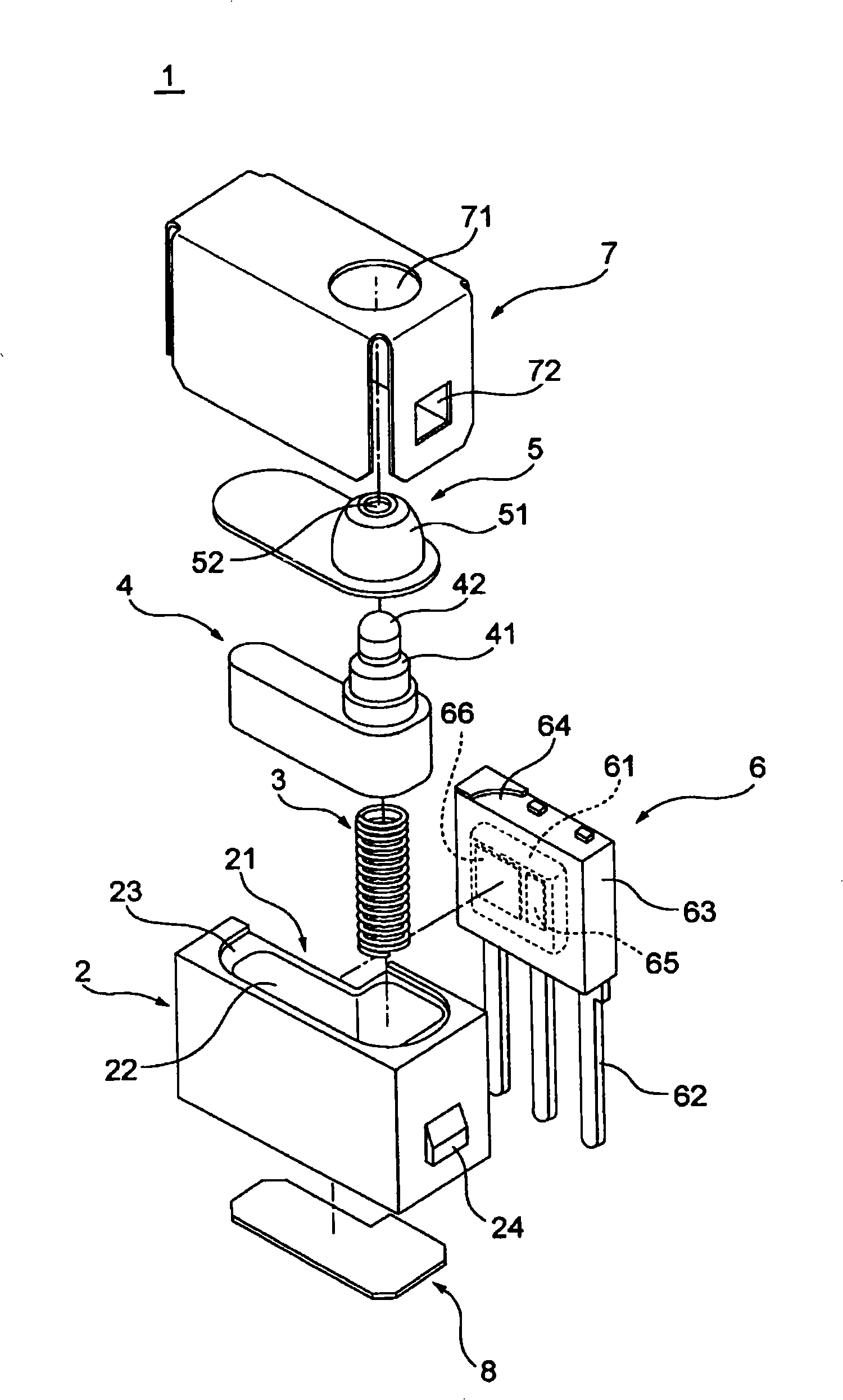
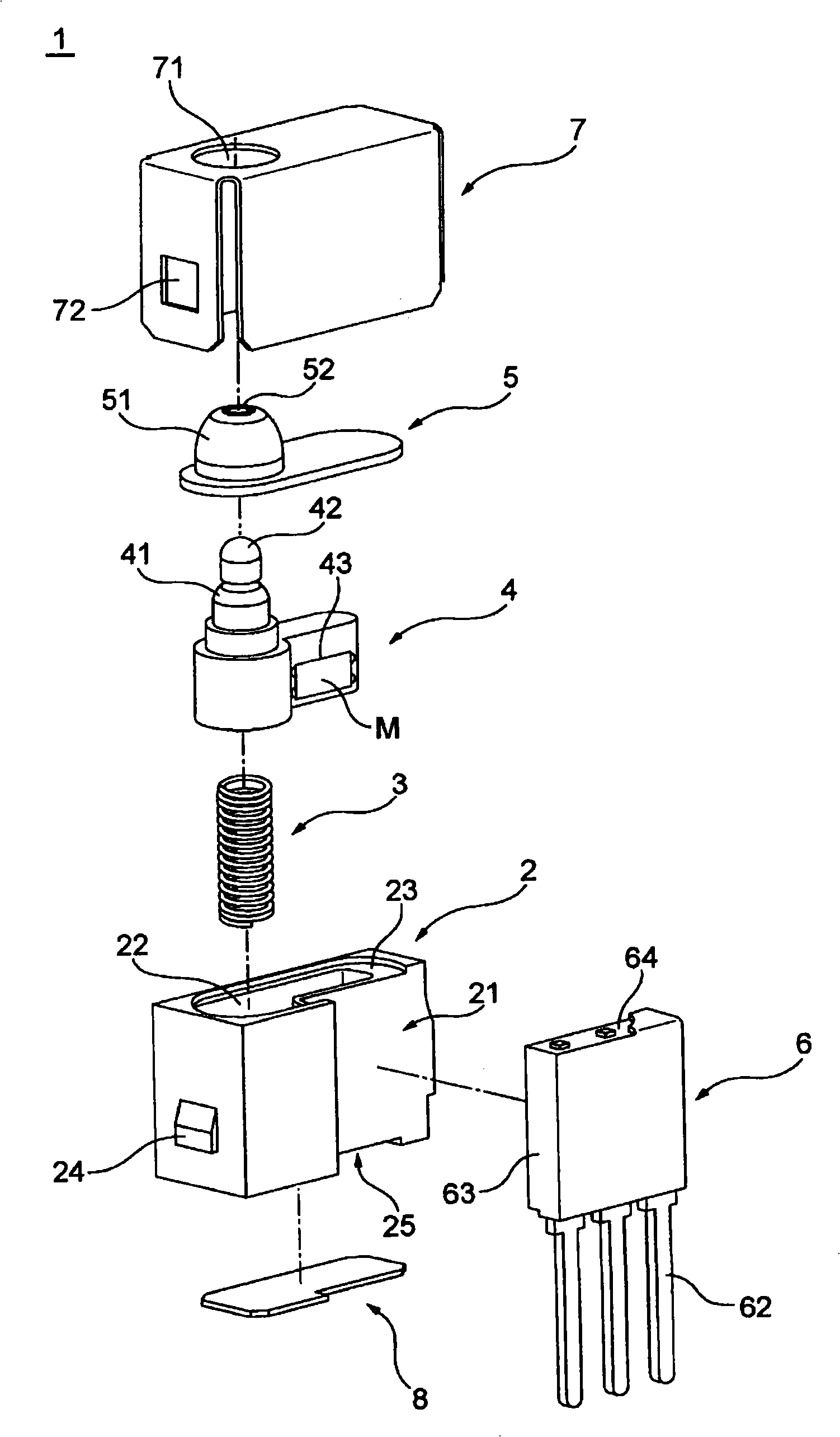
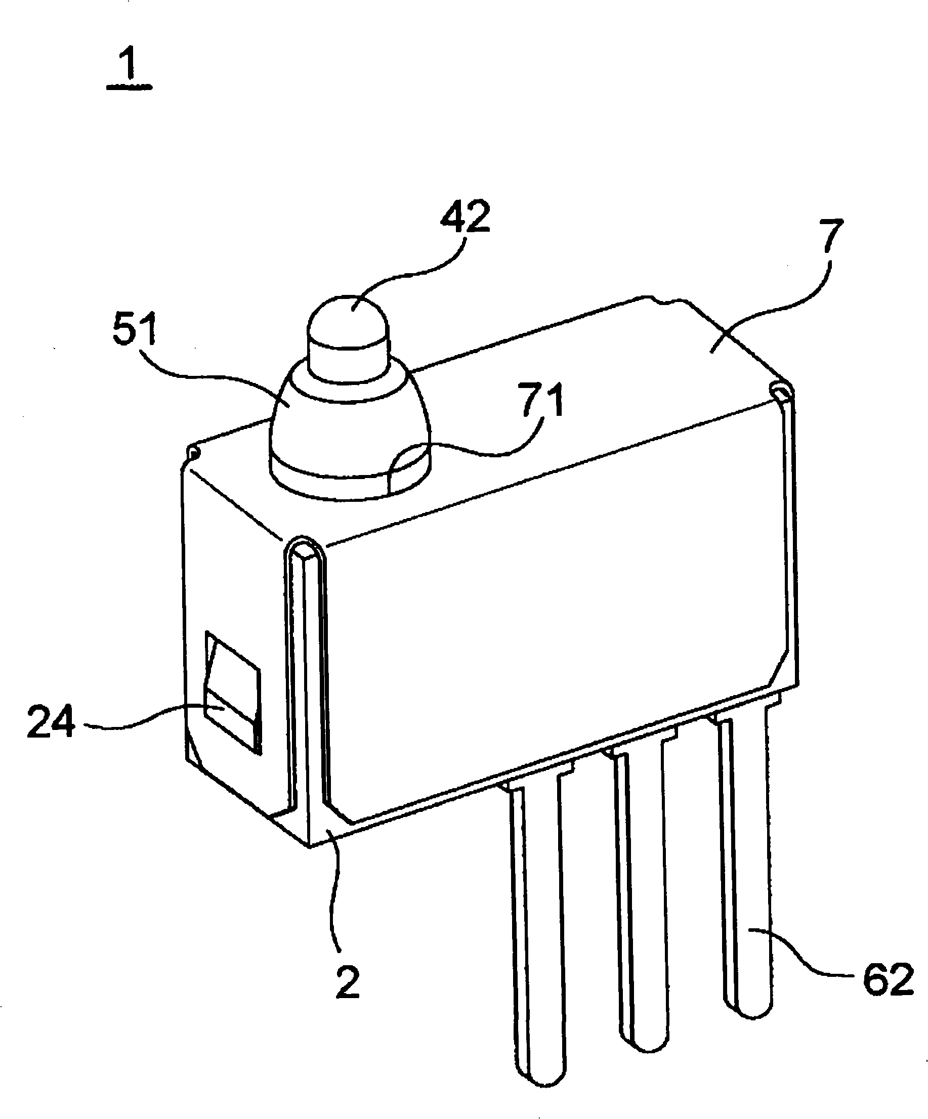
[0031] figure 1 and figure 2 It is an exploded perspective view of the proximity switch device according to the embodiment of the present invention. image 3 It is a perspective view showing the appearance of the proximity switch device of this embodiment. and also, figure 1 and figure 2 The proximity switch device of this embodiment is shown from the opposite sides, respectively.

[0032] like figure 1 and figure 2 As shown, the non-contact switch device 1 of this embodiment includes a housing 2, a compression spring 3 and a slider 4 housed in the housing 2, and a rubber cover 5 placed on the slider 4 housed in the housing 2. , the sensor unit 6 mounted on the housing 2 , the first cover member 7 covering the housing 2 on which the sensor unit 6 is mounted, and the second cover member 8 disposed below the housing 2 while accommodating these compon...


PUM


Abstract

The present invention relates to a non-contact type switching device which can perform on-off operation rapidly even using a GMR element. The non-contact type switching device (1) comprises a magnet (M) reciprocating motion according to operation of manipulator and a GMR element (65) detecting the magnetic field direction coming from the magnet (M), an output signal is switched according the magnetic field direction detected by the GMR element (65), and a magnetization direction of the GMR element (65) is changed according to the magnetic field coming from the magnet (M) only.

Description

technical field [0001] The present invention relates to a non-contact switch device, and more particularly, to a non-contact switch device that switches an output signal by detecting the direction of a magnetic field from a reciprocating magnet with a GMR element. Background technique [0002] Conventionally, a small magnetic induction switch has been proposed, in which a Hall IC, a movable member to which a magnet is fixed, and a coil spring supporting the movable member are arranged in a switch case. When the upper end is pressed, the output signal of the Hall IC is changed from OFF to ON according to the position of the magnet fixed to the movable member (for example, refer to Patent Document 1). [0003] On the other hand, there has been proposed a magnetic sensor utilizing a giant magnetoresistance effect (GMR element) in which an output signal is changed by detecting the direction of a magnetic field from a magnet (for example, refer to Patent Document 2). In a magnet...

Claims


Application Information

Patent Timeline
Patent Type & Authority Applications(China)
IPC IPC(8): H03K17/97
Inventor 泷川真喜人德永一郎仓田孝二
Owner ALPS ALPINE CO LTD
Why Eureka
Try Eureka