Non-invasive railroad attachment mechanism

a technology of attachment mechanism and non-invasive rail, which is applied in the direction of connection contact member material, rail device, way, etc., can solve the problems of brittleness in the track rail, stress concentration within the track rail, and laborious interconnection techniques, so as to facilitate the biasing of the bias force member, facilitate the biasing, and enhance the compressive force

Inactive Publication Date: 2006-02-16
FASTRAX INDS
View PDF4 Cites 16 Cited by
  • Summary
  • Abstract
  • Description
  • Claims
  • Application Information

AI Technical Summary

Benefits of technology

[0009] The anchor may be designed in any manner that allows the first and second members to compressively engage opposing surfaces of the track rail. In one embodiment, the first and second members along with the bias force member define a substantially U-shaped member. Accordingly, a portion of the track rail, such as the flange, may be disposed within the slot defined by the U-shaped member. To facilitate biasing of the bias force member, the slot defined by the U-shaped member may be tapered. Accordingly, by driving a portion of the track rail into the tapered slot the bias force member may be deflected from a static position. To further facilitate such biasing, a strike plate may be incorporated onto a bottom surface of the U-shaped member. This may allow an installer to strike the anchor in order to drive the track rail between the first and second members.
[0010] The bias force member may be a separately formed member that interconnects the first and second members. In another arrangement, the first member, second member and the bias force member may be an integrally formed unit. In either arrangement, the bias force member acts effectively as a spring that interconnects the first and second members. As will be appreciated, the restoring force (i.e., compressive force) provided by the bias force member may be selected in accordance with design requirements. For instance, one or more physical parameters of the bias force member may adjusted to, for example, stiffen the bias force member such that is may provide an enhanced compressive force between the first and second members if so desired.

Problems solved by technology

Such interconnection techniques are generally labor intensive and require careful positioning to prevent structurally weakening the track rail.
Such connection techniques can result in a stress concentration within the track rail.
Further, the heat of exothermic connectors (welding) can result in a brittleness in the track rail.
As will be appreciated, track rails are subjected to repeated heavy loading (e.g., railroad traffic) and areas including such stress concentrations and / or brittleness may be subject to failure.

Method used


Image

  • Non-invasive railroad attachment mechanism
  • Non-invasive railroad attachment mechanism
  • Non-invasive railroad attachment mechanism

Examples


Embodiment Construction

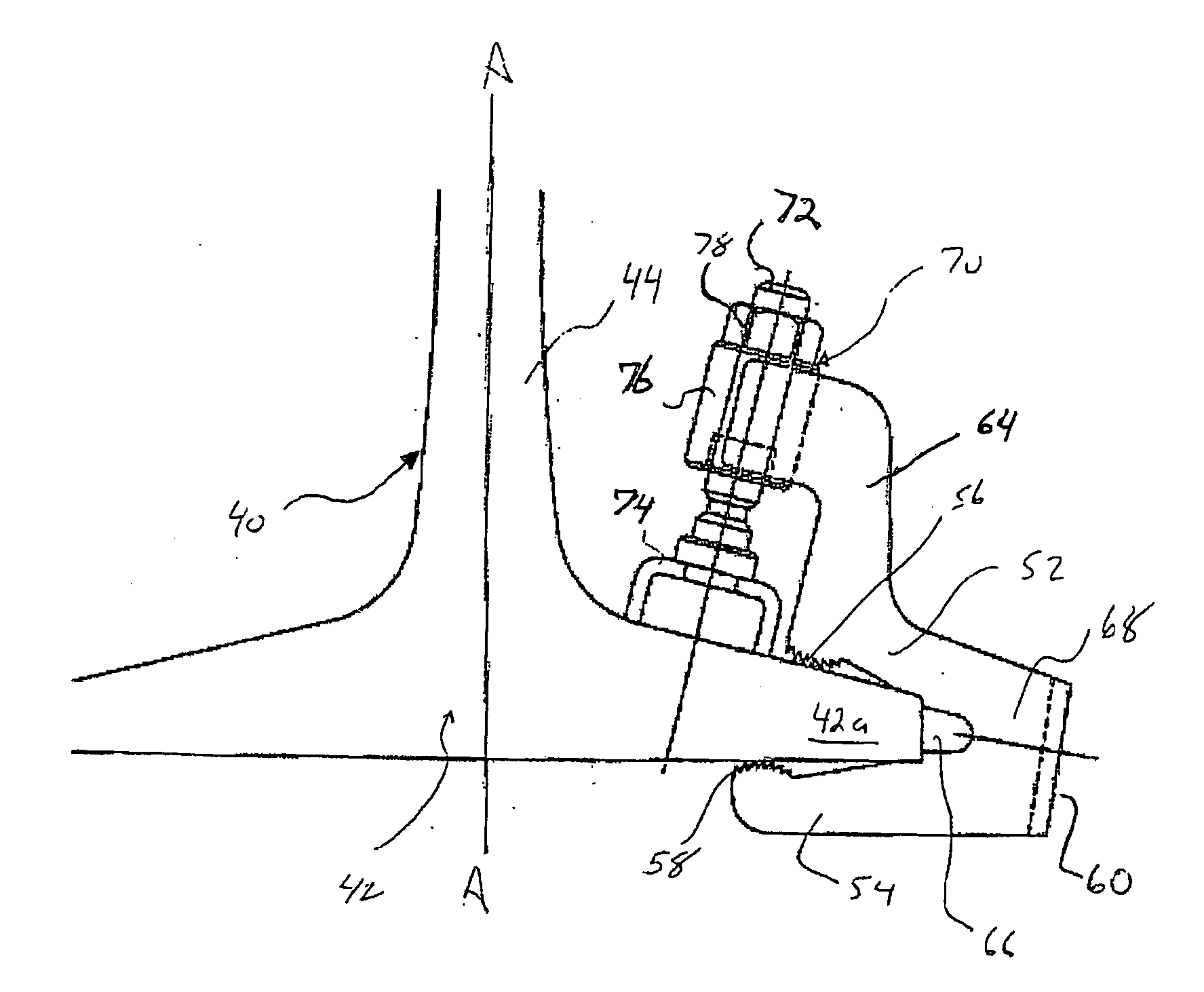
[0037] The present invention is directed to various anchoring / clamping mechanisms that permit non-invasively holding a component relative to the surface of a railroad track rail. The anchoring mechanisms are operable to hold a variety of different components relative to the surface of such track rails. However, in the following description the invention is set forth primarily in the context of non-invasively holding a heater element and / or a signal line / conductor relative to the surface of a track rail. It will be appreciated, however, that certain aspects of the invention are not limited to such applications.

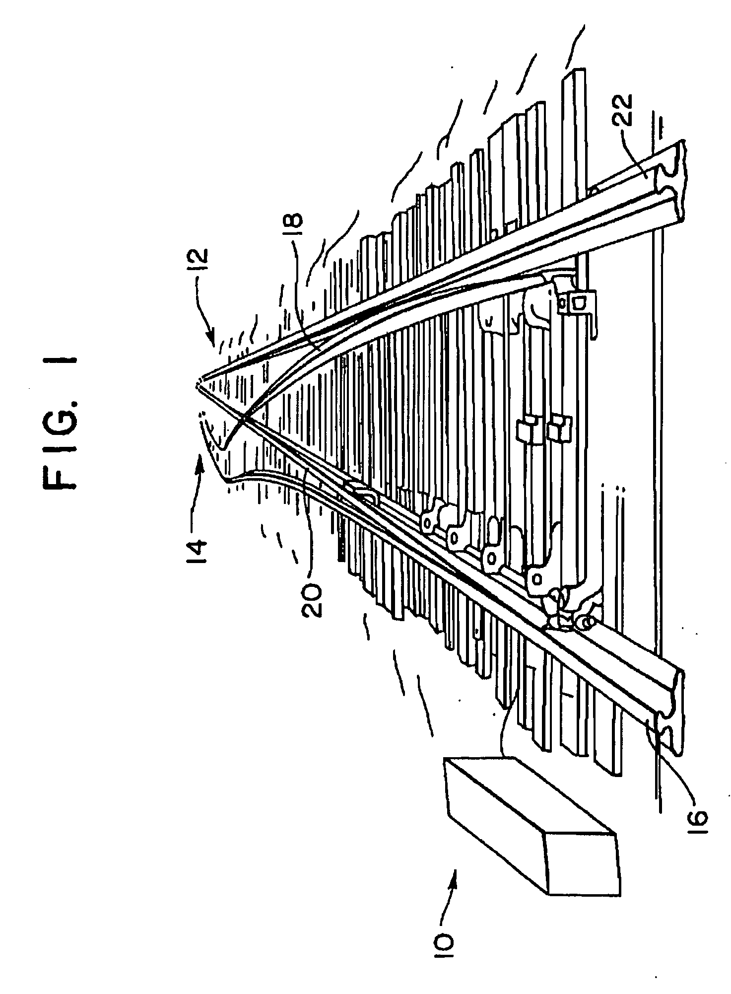
[0038] Referring to FIG. 1, a railroad track switch is generally identified by the reference numeral 10. The track switch 10 is used, for example, to switch train traffic between first 12 and second 14 tracks. Generally, the switch 10 includes a pair of fixed rails 16 and 22 and a pair of switching rails 18 and 20.

[0039] The switching rails 18 and 20 are positioned on the gau...


PUM


Abstract

The present invention relates to a system and method for non-invasively attaching components to railroad track rails. More specifically, an anchor is provided that securely fastens to the track rail in a non-invasive manner for holding one or more components relative to a surface of the track rail. In one embodiment, the non-invasive anchor utilizes a compressive force to clamp to a flange portion of the track rail. Once securely clamped to the track rail, an adjustable track engaging member is utilized to hold a component relative to the surface of the track rail. In this regard, the track engaging member may be advanced toward the track rail to compress the component between a portion of the anchor and a surface of the track rail. In another embodiment, the anchor is adhesively attachable to a surface of the track rail.

Description

CROSS REFERENCE TO RELATED APPLICATIONS [0001] This application claims priority under 35 U.S.C. 119 to U.S. Provisional Application No. 60 / 600,182 entitled: “Non-invasive Railroad Attachment Mechanism,” having a filing date of Aug. 10, 2004.FIELD OF THE INVENTION [0002] The present invention relates to a system and method for securely attaching components to railroad track rails without affecting the structural integrity of the track rails. More specifically, an anchor is provided that securely fastens to a track rail in a non-invasive manner for holding one or more components relative to a surface of the track rail. BACKGROUND OF THE INVENTION [0003] In railroad applications, it is often desirable to attach one or more components to the track rail. A non-inclusive list of such components includes communications wires (i.e., signal conductors) and track heaters. In the latter case, such track heaters are often utilized in cold weather climates at railroad switches. [0004] Components...

Claims


Application Information

Patent Timeline
Patent Type & Authority Applications(United States)
IPC IPC(8): B60M1/00
CPCB60M1/30H01R4/66H01R4/304B60M5/00
Inventor REICHLE, DAVID L.
Owner FASTRAX INDS
Why Eureka
Try Eureka