
Huber safety needle

a safety needle and huber technology, applied in the direction of catheters, infusion needles, other medical devices, etc., can solve the problems of presenting a considerable risk to the user of such a huber needle assembly, significant risk of inadvertent needle-stick injury to the first hand, and further risk of needle-stick injury to the user, so as to prevent rebound and prevent needle-stick injury

Active Publication Date: 2017-09-21
MEDICAL COMPONENTS INC
View PDF4 Cites 2 Cited by
  • Summary
  • Abstract
  • Description
  • Claims
  • Application Information

AI Technical Summary

Benefits of technology

The Huber needle assembly is designed to safely hold and extract a needle. It includes an upper body and lower body that move relative to each other, allowing for easy insertion and extraction of the needle. The lower body has a catch that engages the needle to prevent it from moving in an unsafe manner. The assembly can be designed to prevent exposure of the needle tip and minimize injury risk. It can also be designed to cause the needle to move in a forward or rearward direction, depending on the needs of the user. The assembly can be connected by a connector that limits the separation distance between the upper body and lower body to prevent the needle tip from extending beyond the lower body. Overall, the Huber needle assembly provides a safe and effective tool for needle insertion and extraction.

Problems solved by technology

The known Huber needle assembly may be designed for safety of the patient; however, it presents a considerable risk to the user of such a Huber needle assembly.
For example, use of a known Huber needle assembly can expose the user to blood borne pathogens, drugs, and / or medication being administered through the Huber needle, regardless of whether the known Huber needle assembly is used properly or improperly.
Removal of the needle while the first hand is in the area of the insertion site can present a significant risk of inadvertent needle-stick injury to the first hand.
Further, the force required to withdraw the needle from a self-sealing septum of the implanted port can cause a user to over-extend the structure of the known Huber needle assembly, whereby the resilient nature of the material comprising the structure causes the needle to rebound, resulting in further risk of a needle-stick injury to the user.
Such a needle-stick injury can result in transfer of blood borne pathogens, such as Hepatitis, Human Immunedeficiency Virus (“HIV”), etc.
In addition to blood borne pathogens, healthcare workers that prepare hazardous drugs, mix drugs, and / or administer drugs can be at risk for exposure to the drug if such a needle-stick injury occurs.
Even when drugs are carefully handled, exposure can result from inhalation or direct skin contact with the drug due to exposure to the needle tip.

Method used


Image

  • Huber safety needle
  • Huber safety needle
  • Huber safety needle

Examples


Embodiment Construction

[0027]The following description is of an embodiment presently contemplated for carrying out the present invention. This description is not to be taken in a limiting sense, but is made merely for the purpose of describing the general principles and features of the present invention. The scope of the present invention should be determined with reference to the claims.

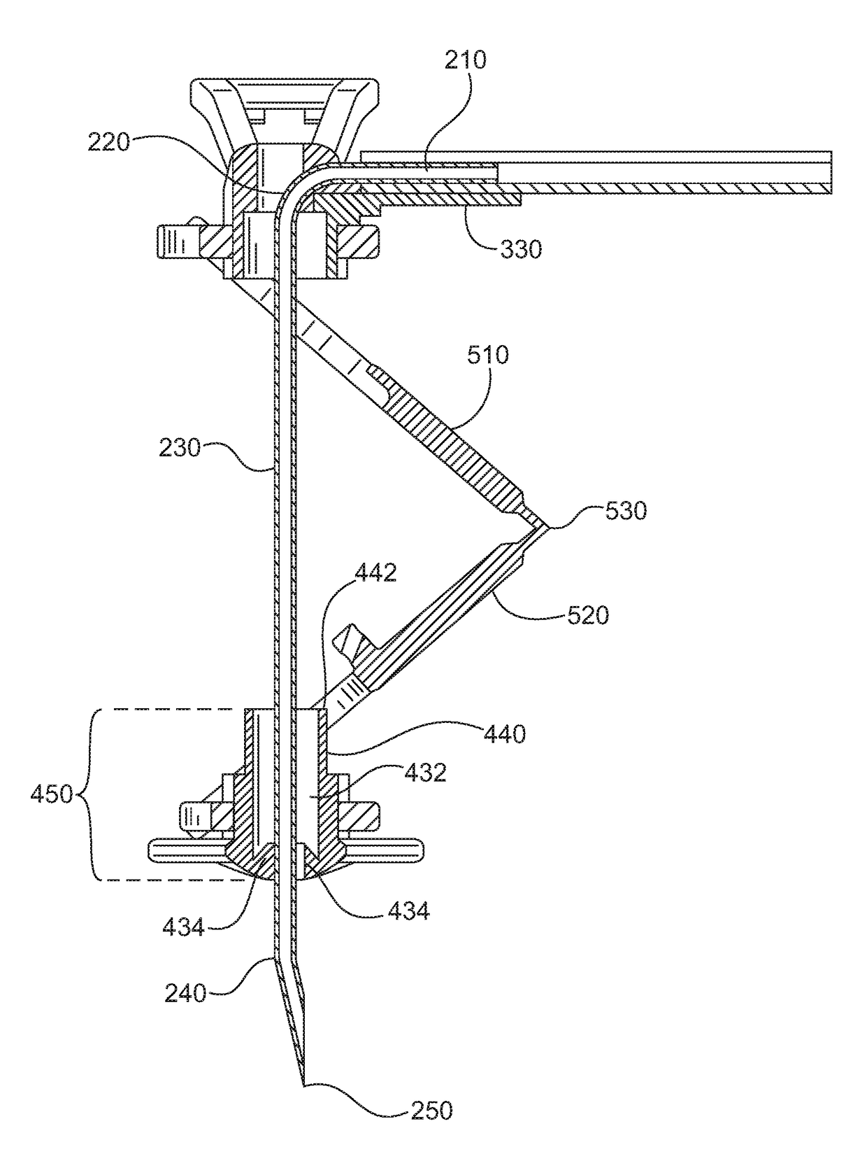
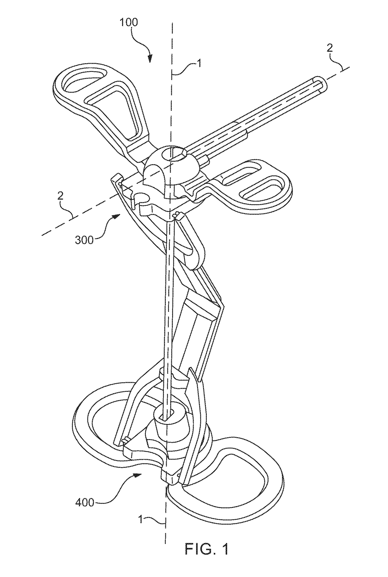
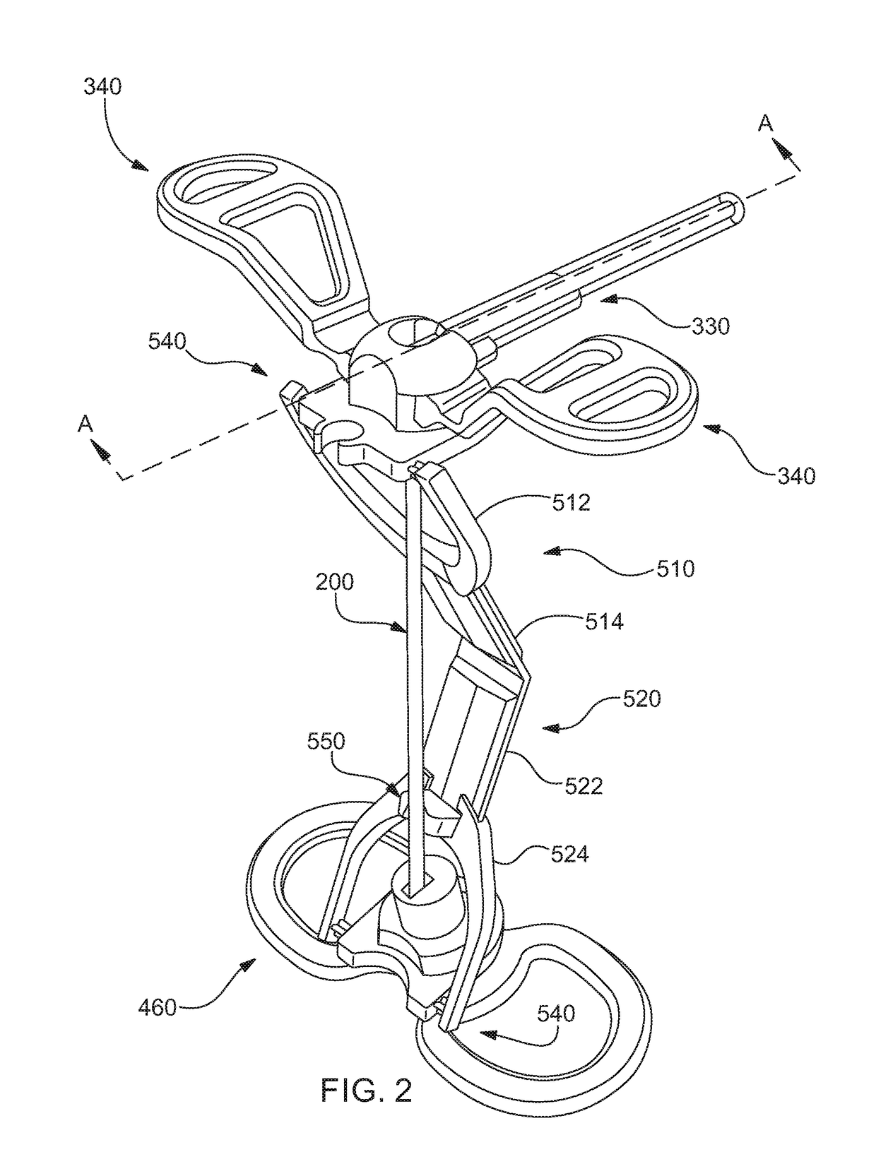
[0028]The Huber needle assembly 100 is an apparatus that may be structured to provide support for a needle 200 and facilitate insertion / extraction of the needle 200 into / therefrom a body of a being. In some embodiments, the assembly 100 can be structured to support a Huber style needle 200. In further embodiments, the assembly 100 can be structured to facilitate insertion / extraction of a needle 200 into / therefrom an implantable port (not shown) that may have been implanted into the body of the being.

[0029]The assembly 100 can include an upper body 300 and a lower body 400, and may be configured such that the upper body 30...


PUM


Abstract

Disclosed is a Huber needle assembly that may include an upper body connected to a lower body, the assembly being structured to retain a needle for insertion / extraction of the needle into / from an insertion site. The upper body can statically retain the needle while the lower body may slidably receive the needle. The lower body can further include a catch that engages a tip of the needle and / or misaligns the tip of the needle with a needle aperture of the lower body to place the assembly in a safety-lock position, preventing rebound, needle-stick injury, and / or any type of exposure of the needle tip to an environment outside of the lower body. The assembly can further bias the needle in a direction so as to prevent re-emergence of the needle tip after being withdrawn into the lower body.

Description

CROSS-REFERENCES TO RELATED APPLICATIONS[0001]This application claims the benefit of priority to U.S. Provisional application No. 62 / 310,130 filed on Mar. 18, 2016 and U.S. Provisional application No. 62 / 407,137 filed on Oct. 12, 2016, the entire contents of which are incorporated herein by reference.BACKGROUND OF THE INVENTION[0002]Field of the Invention[0003]The subject matter disclosed herein generally relates to a Huber needle assembly. More specifically, the subject matter herein relates to a Huber needle assembly with a means to generate a safety-lock position by biasing the needle away from the needle aperture to prevent re-emergence of the needle tip from the assembly.[0004]Background of the Related Art[0005]Known Huber needle assemblies are generally widely used in hospitals and alternate care sites, where these Huber needle assemblies are generally used in conjunction with implanted ports. Such Huber needle assemblies can provide a non-coring needle that may be used to adm...

Claims


Application Information

Patent Timeline
IPC IPC(8): A61M5/32A61M5/31A61M5/34
CPCA61M5/3232A61M5/3221A61M2205/581A61M5/3137A61M2005/342A61M5/34A61M5/158A61M2005/1583A61M2005/1585A61M2005/1586A61M5/3243A61M5/3275A61M2005/1581A61M2005/3247A61M25/0612A61M25/0625
Inventor SHIMER, KURTGUNN, MATTHEWBIZUP, RAYMOND
Owner MEDICAL COMPONENTS INC
Learn More