Expansion ring assembly with removable drive mechanism

a technology of drive mechanism and expansion ring, which is applied in the direction of snap fasteners, cable terminations, buckles, etc., can solve the problems of increasing the overall cost of each expansion ring assembly, heavy and cumbersome use of hydraulic drive devices and scissor-type installation tools in the field during installation,

Active Publication Date:
View PDF26 Cites 16 Cited by
  • Summary
  • Abstract
  • Description
  • Claims
  • Application Information

AI Technical Summary

Benefits of technology

[0014] In another form thereof, the present invention provides an expansion ring assembly, including a ring including a pair of end portions, at least one of the end portions including first ratcheting structure; an oversleeve disposed in overlapping relationship with the ring end portions, the oversleeve including a pair of opposite ends, at least one of the opposite ends having second ratcheting structure in respective engagement with the first ratcheting structure of the ring end portions; and a drive mechanism, including a pair of block members each having a threaded bore therein, the bores of the block members being oppositely threaded, the block members removably engaged with respective end portions of the ring; and a bolt including oppositely-threaded ends respectively threaded within the bores of the block members, whereby rotation of the bolt in a first direction causes the block members to be simultaneously driven apart from one another to thereby expand the ring and sequentially engage the first ratcheting structure of the ring end portion with the second ratcheting structure of the oversleeve.

Problems solved by technology

Although the foregoing expansion ring assembly is effective for installing a gasket within an opening in a structure, the scissors-type installation tool and hydraulic drive device can be heavy and cumbersome to use in the field during installation.
This increases the overall cost of each expansion ring assembly.

Method used


Image

  • Expansion ring assembly with removable drive mechanism
  • Expansion ring assembly with removable drive mechanism
  • Expansion ring assembly with removable drive mechanism

Examples


Embodiment Construction

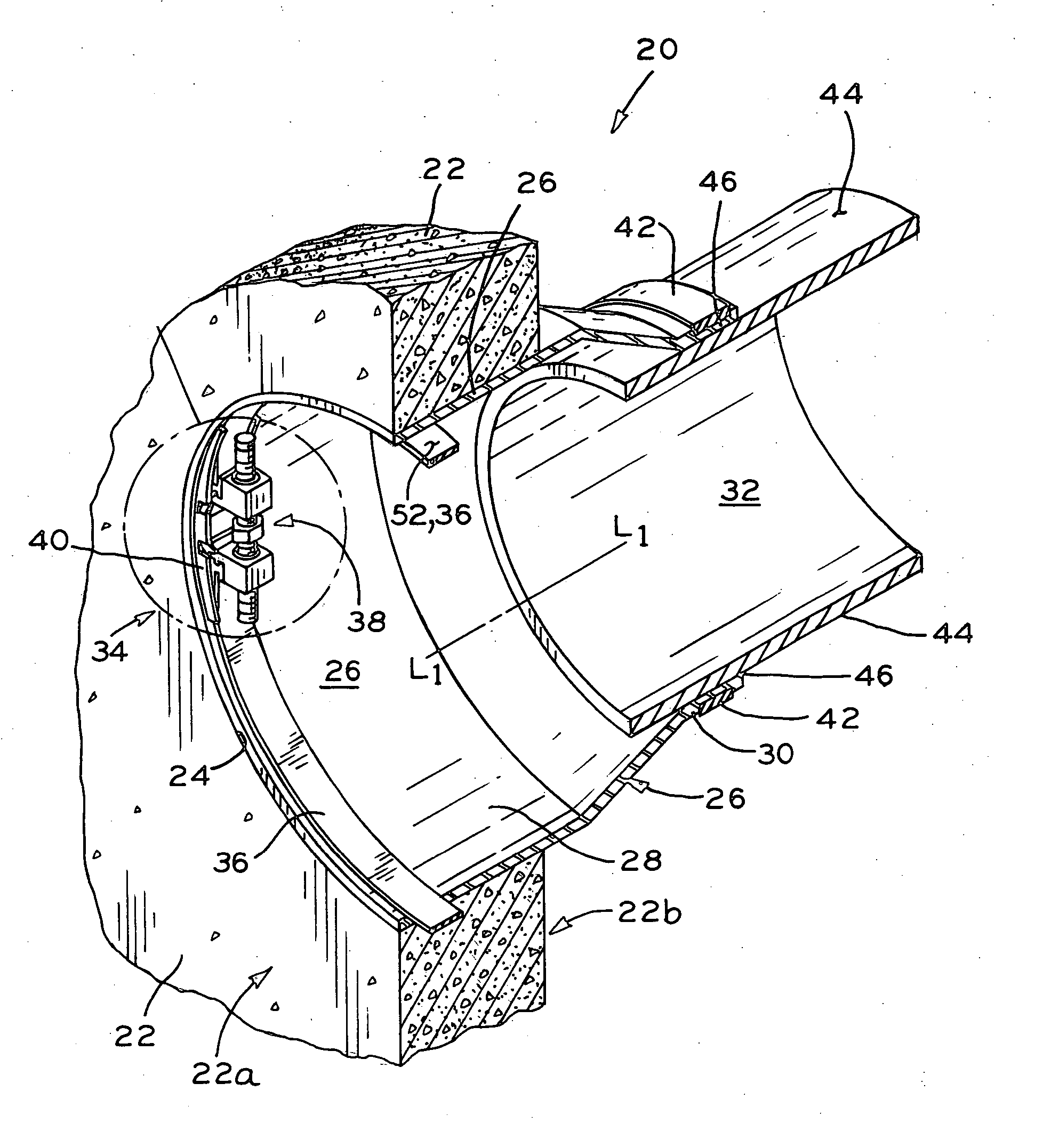
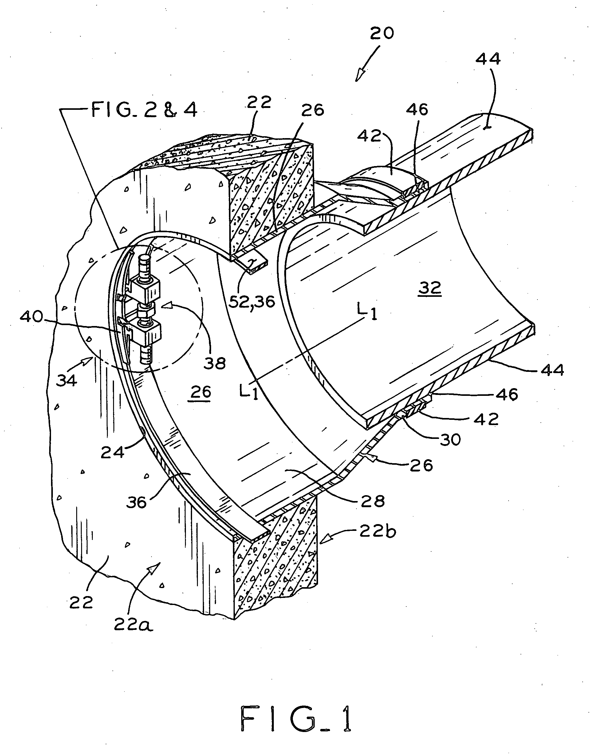
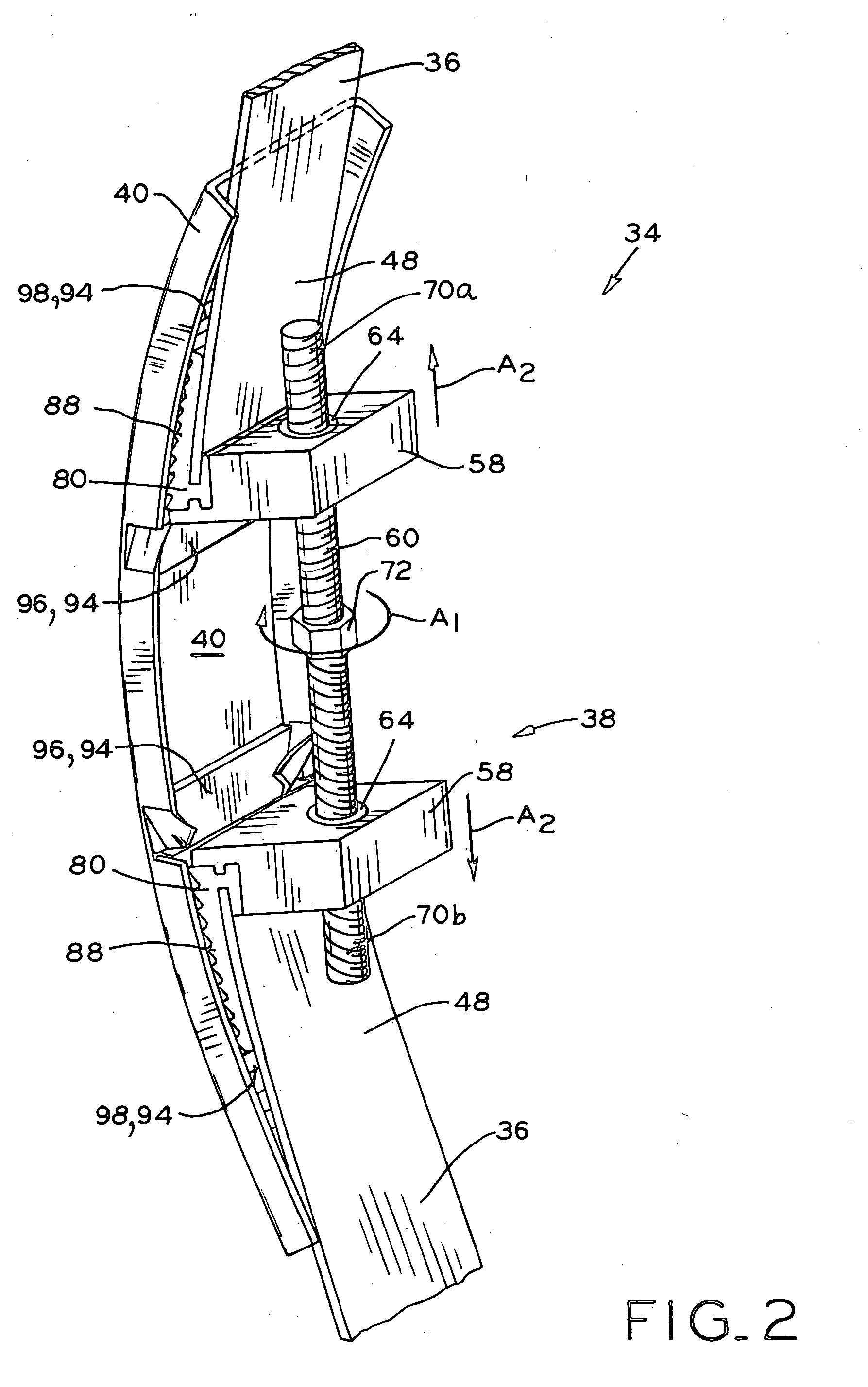
[0022] Referring to FIG. 1, pipe connection 20 in an underground pipe system is shown, in which a pipe is connected to a structure, such as a manhole riser or monolithic base, for example. The structure may be formed of concrete, fiberglass, or any other suitable rigid material. The structure includes wall 22 having interior side 22a defining the interior of the structure, and exterior side 22b defining the exterior of the structure. Additionally, wall 22 includes annular opening 24. An annular gasket 26 includes a first portion 28 disposed within opening 24 of wall 22, and a second portion 30 extending from first portion 28. Gasket 26 may be made from a flexible, elastomeric material such as rubber or neoprene, for example, and provides a sealing connection between opening 24 in wall 22 of the structure and a pipe 32. First portion 28 of gasket 26 is sealingly engaged with opening 24 of wall 22 by expansion ring assembly 34, which generally includes expansion ring 36, drive mechani...


PUM


Abstract

An expansion ring assembly for sealing a gasket within an opening in the wall of a structure, the assembly including a drive mechanism having a pair of block members each having a threaded bore, and a bolt having oppositely threaded ends respectively threaded within the bores. The block members are removably engaged with respective ends of the expansion ring. An oversleeve is disposed in overlapping relationship with the expansion ring ends, and the expansion ring ends and the oversleeve include cooperating ratcheting structures. Rotation of the bolt of the drive mechanism in a first direction causes the block members to move outwardly along the bolt to expand the expansion ring and concurrently sequentially engage the ratcheting structures of the expansion ring ends and the oversleeve. Once the expansion ring is expanded to a desired extent, the bolt of the drive mechanism may be rotated in a second direction opposite the first direction to move the block members inwardly along the bolt and allow disengagement of the block members from the expansion ring ends and removal of the drive mechanism. The expansion ring ends are maintained in their expanded condition by the engagement of the ratcheting structures of the expansion ring ends and the oversleeve. In another embodiment, overlapping ends of the expansion ring have ratcheting structure therebetween, and are driven apart by the removable the drive mechanism, wherein the oversleeve member is eliminated.

Description

CROSS REFERENCE TO RELATED APPLICATIONS [0001] This application claims the benefit under Title 35, U.S.C. §119(e) of U.S. Provisional Patent Application Ser. No. 60 / 600,543, entitled EXPANSION RING ASSEMBLY WITH REMOVABLE DRIVE MECHANISM, filed on Aug. 11, 2004.BACKGROUND OF THE INVENTION [0002] 1. Field of the Invention [0003] The present invention relates to an expansion ring assembly, and associated method, for sealing an annular gasket to a rigid structure. [0004] 2. Description of the Related Art [0005] In underground pipe systems, it is often necessary to connect a pipe in a sealed manner within an opening in the wall of a rigid structure, such as a manhole riser or monolithic base, for example. Typically, an annular, flexible elastomeric gasket is placed within the opening in the wall, followed by fitting an expansion ring against the interior surface of the gasket. Thereafter, an expansion mechanism is used to radially expand the expansion ring and lock same in an expanded c...

Claims


Application Information

Patent Timeline
Patent Type & Authority Applications(United States)
IPC IPC(8): F16L49/00
CPCF16L5/02F16L41/002Y10T24/1441F16L55/163F16L41/088
Inventor NEUHAUS, RONALD W.HAPPEL, ANDREW J.
Why Eureka
Try Eureka