RF coil for imaging system

a technology of imaging system and rf coil, which is applied in the direction of diagnostic recording/measuring, using reradiation, instruments, etc., can solve the problems of high resolution, insufficient signal to noise ratio, and inefficient operation of conventional bird cage coil with lumped elements (reactance), so as to improve the control of field profile, improve the tuning option, and improve the effect of detuning

Inactive Publication Date: 2006-02-16
THE GENERAL HOSPITAL CORP
View PDF89 Cites 16 Cited by
  • Summary
  • Abstract
  • Description
  • Claims
  • Application Information

AI Technical Summary

Benefits of technology

The patent text discusses the advantages of distributed impedance RF coils, which are similar to those in previous patents. However, these systems do not always provide optimal performance in all situations. The text suggests improvements that can be made to the RF coils, including better suppression of eddy currents, better positioning for a wider range of cases, better control of field profile, better tuning options, and better detuning in cases where multiple coils are needed.

Problems solved by technology

The technical problem addressed in this patent text is the need for an RF coil design that can improve the signal-to-noise ratio and spectral resolution in imaging and spectroscopy applications. The current coils used in existing systems have limitations in terms of their ability to achieve high field strength operation, to suppress eddy currents, and to tune to precise resonant frequencies. The invention aims to design an RF coil that can overcome these limitations and provide better performance in various imaging applications.

Method used


Image

  • RF coil for imaging system
  • RF coil for imaging system
  • RF coil for imaging system

Examples


Embodiment Construction

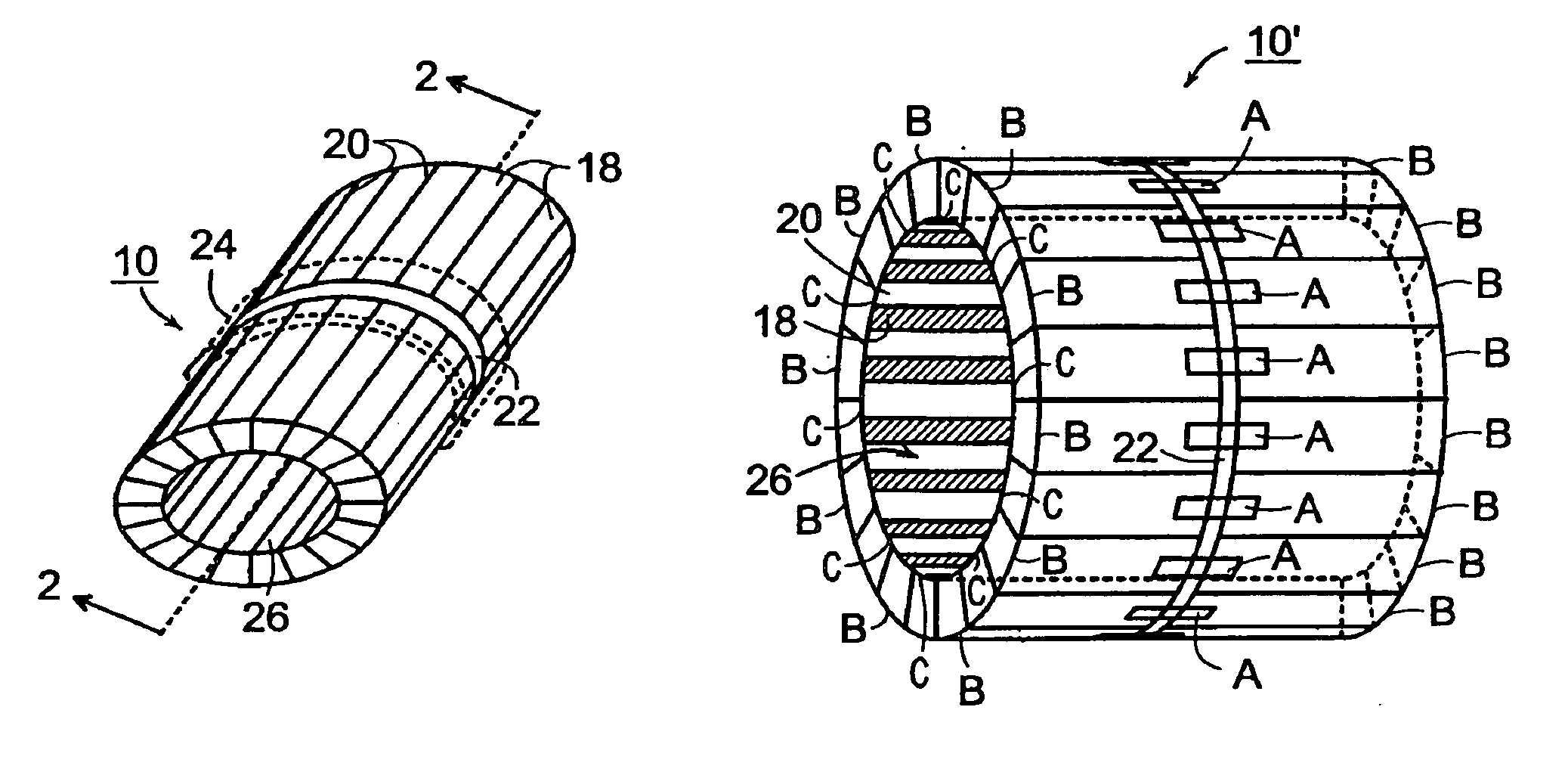
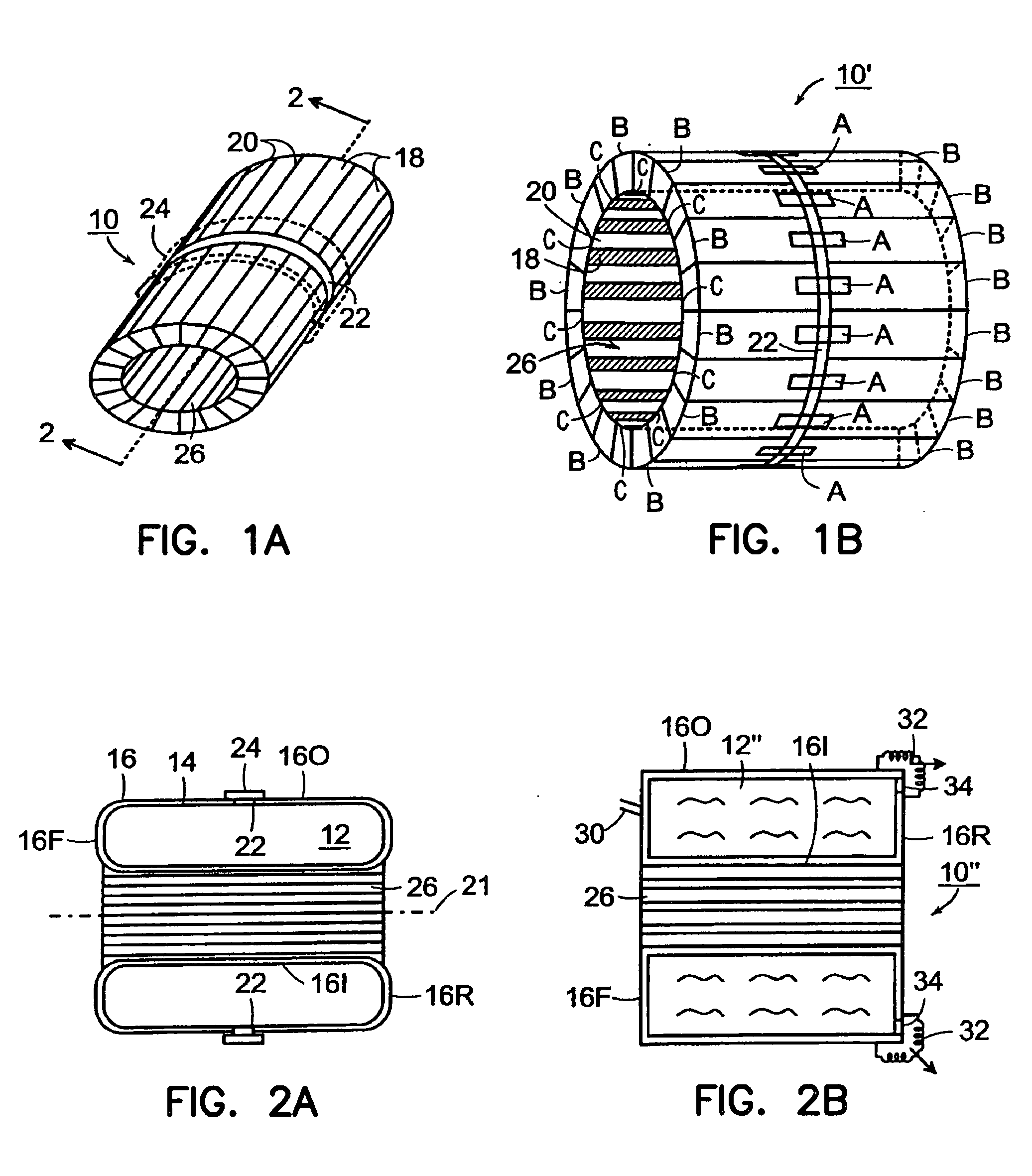
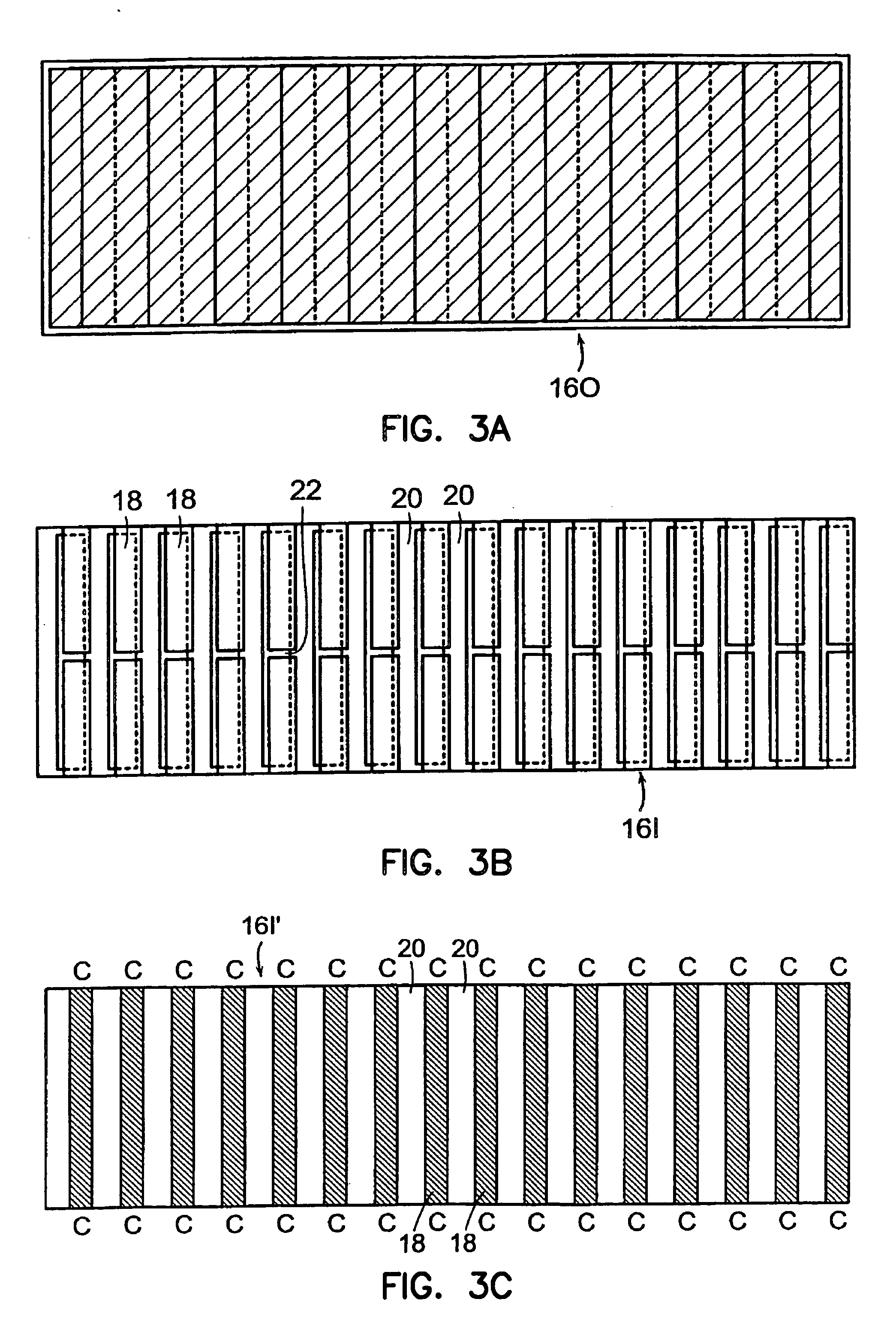
[0042]FIGS. 1A and 2A show an illustrative embodiment of the invention which overcomes many of the problems discussed earlier. In particular, the RF coil 10 shown in these figures has a conducting cavity formed as a conductive enclosure 12 in which resonant field can be excited, the enclosure being formed by a surrounding, conducting wall 16, which wall may be supported by a non-conducting wall 14. Conducting wall 16 may be a whole wall which is at least selectively patterned as described later, or may be formed of conducting tubes, coaxial tubes as in the U.S. Pat. No. 5,557,247 or other appropriate spaced components. Cavity / enclosure 12 is filled with air or another dielectric material and supporting wall 14 may also be formed of a dielectric material having a dielectric constant which substantially matches that of the material in cavity 12. Cavity 12 may also be defined by a solid piece of dielectric material of the appropriate shape.

[0043] The enclosure or cavity 12 may have a ...


PUM


Abstract

An RF coil suitable for use in imaging systems is provided which coil has a dielectric filled cavity formed by a surrounding conducting enclosure, the conducting enclosure preferably being patterned to form continuous electrical paths around the cavity, each of which paths may be tuned to a selected resonant frequency. The patterning breaks up any currents inducted in the coil and shortens path lengths to permit higher frequency, and thus higher field strength operation. The invention also includes improved mechanisms for tuning the resonant frequency of the paths, for selectively detuning the paths, for applying signal to the coil, for shortening the length of the coil and for controlling the field profile of the coil and the delivery of field to the object to the image.

Description


Claims


Application Information

Patent Timeline
Owner THE GENERAL HOSPITAL CORP
Why Eureka
Try Eureka