Large diameter D-shaped optical waveguide and coupler

Inactive Publication Date: 2006-02-07
CIDRA CORP SERVICES
View PDF54 Cites 23 Cited by
  • Summary
  • Abstract
  • Description
  • Claims
  • Application Information

AI Technical Summary

Benefits of technology

[0004]Objects of the present invention include provision of an optical waveguide

Problems solved by technology

However, in such cases, the fiber is either highly lossy or very difficult to manufacture and/or very difficult to use because they are very delicate and fragile.
In particular, when

Method used


Image

  • Large diameter D-shaped optical waveguide and coupler
  • Large diameter D-shaped optical waveguide and coupler
  • Large diameter D-shaped optical waveguide and coupler

Examples


Embodiment Construction

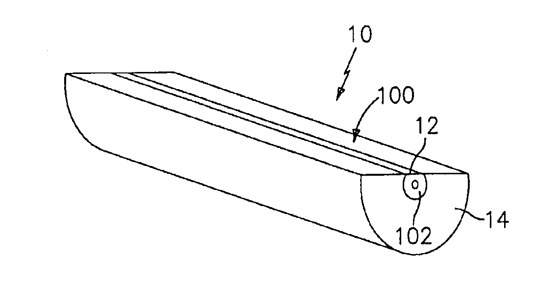
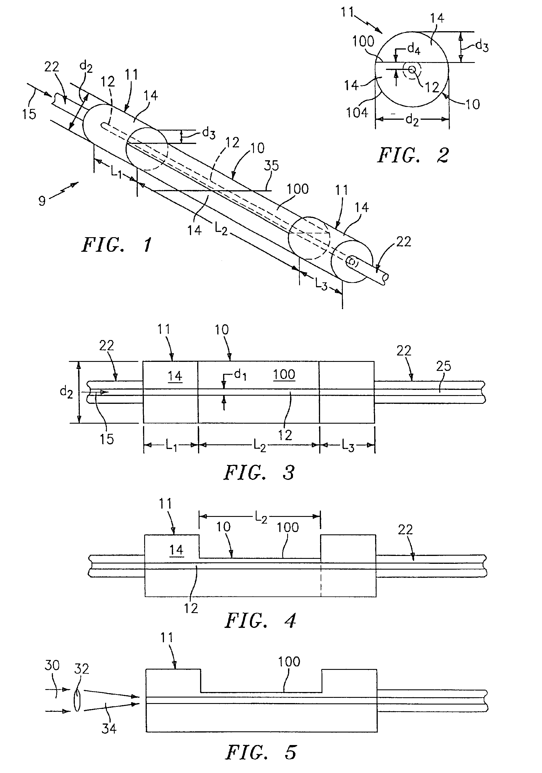
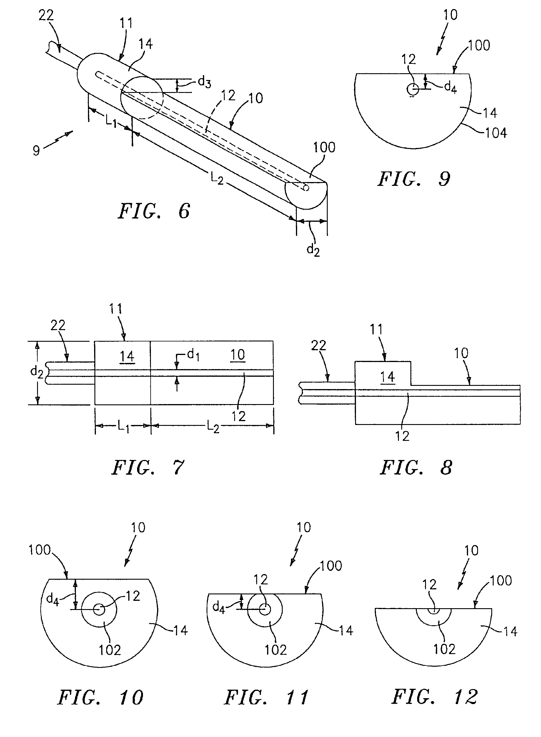
[0043]Referring to FIGS. 1-4, a large diameter D-shaped optical waveguide device 9, has a D-shaped waveguide portion 10, a circular waveguide portion 11, and has at least one core 12 surrounded by a cladding 14. The waveguide device 9 comprises silica glass (SiO2) based material having the appropriate dopants, as is known, to allow light 15 to propagate in either direction along the core 12 and / or within the waveguide device 9. The core 12 has an outer dimension d1 and the waveguide device 9 has an outer dimension d2.

[0044]The cladding 14 has an outer dimension d2 of at least about 0.3 mm and the core 12 has an outer dimension d1 such that it propagates only a few spatial modes (e.g., less than about 6). For example for single spatial mode propagation, the core 12 has a substantially circular transverse cross-sectional shape with a diameter d1 less than about 12.5 microns, depending on the wavelength of light. One standard telecommunications nominal core diameter is 9 microns (and o...


PUM


Abstract

A large diameter D-shaped optical waveguide device 9, includes an optional circular waveguide portion 11 and a D-shaped waveguide portion 10 having at least one core 12 surrounded by a cladding 14. A portion of the waveguide device 9 has a generally D-shaped cross-section and has transverse waveguide dimension d2 greater than about 0.3 mm. At least one Bragg grating 16 may be impressed in the waveguide 10 and/or more than one grating or pair of gratings may be used and more than one core may be used. The device 9 provides a sturdy waveguide platform for coupling light into and out of waveguides and for attachment and alignment to other waveguides, for single and multi-core applications. The core and/or cladding 12,14 may be doped with a rare-earth dopant and/or may be photosensitive. At least a portion of the core 12 may be doped between a pair of gratings 50,52 to form a fiber laser or the grating 16 or may be constructed as a tunable DFB fiber laser or an interactive fiber laser within the waveguide 10. The waveguide may resemble a short “block” or a longer “cane” type, depending on the application and dimensions used.

Description

CROSS REFERENCES TO RELATED APPLICATIONS[0001]This application is a continuation-in-part of U.S patent application Ser. No. 09 / 455,868, filed Dec. 12, 1999, which is a continuation-in-part of U.S patent application Ser. No. 09 / 455,865, filed Dec. 6, 1999, which is a continuation-in-part of U.S. patent application Ser. No. 09 / 399,495, filed Sep. 20, 1999, now abandoned, which is continuation in part of U.S. patent application Ser. No. 09 / 205,943, filed Dec. 4, 1998, now abandoned; and claims the benefit of U.S. Provisional Application No. 60 / 276,457, filed Mar. 16, 2001, all of which are incorporated herein by reference in their entirety.TECHNICAL FIELD[0002]This invention relates to optical waveguides and couplers, and more particularly to optical waveguides and couplers, having a large outer diameter and substantially D-shaped.BACKGROUND ART[0003]It is known that optical fibers having non-circular cross-sectional outer shapes, such as a D-shaped fiber, are used for various purposes...

Claims


Application Information

Patent Timeline
IPC IPC(8): G02B6/02G02B6/34H01S3/067G02B6/00G01L1/24G02B6/28G02B6/42H01S3/094
CPCG01L1/242G02B6/02057G02B6/274G02B6/2817G02B6/2821H01S3/0675G02B6/2826H01S3/094019G02B6/4214H01S3/06708H01S3/094003H01S3/094007G02B6/29334
Inventor BAILEY, TIMOTHY J.BRUCATO, ROBERT N.KERSEY, ALAN D.PUTNAM, MARTIN A.SANDERS, PAULSULLIVAN, JAMES
Owner CIDRA CORP SERVICES
Why Eureka
Try Eureka