
Systems and methods using computer vision and capacitive sensing for cursor control

a capacitive sensing and cursor control technology, applied in computing, portable computers, instruments, etc., can solve the problems of difficulty in determining when the user's action is, remains problematic and ineffective in distinguishing a user's intentional movement, and cannot be easily determined. , to achieve the effect of facilitating determining the hand, being more stable and smoother

Inactive Publication Date: 2006-02-16
MICROSOFT TECH LICENSING LLC
View PDF7 Cites 164 Cited by
  • Summary
  • Abstract
  • Description
  • Claims
  • Application Information

AI Technical Summary

Benefits of technology

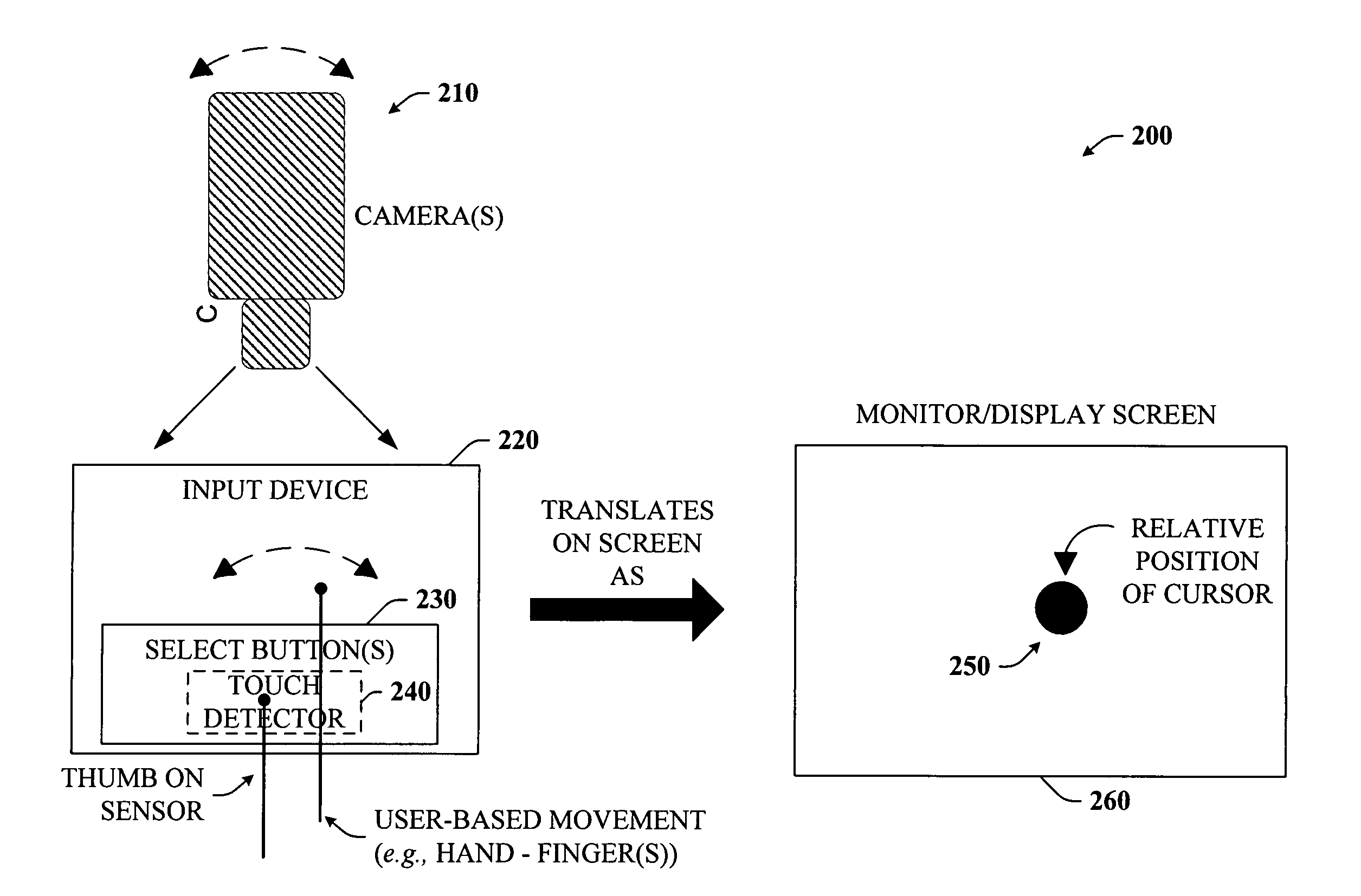
[0007] According to another aspect of the invention, flow fields can be employed to compute relative motion of a user's hand(s). In particular, flow fields can be computed on the image in real time. Rather than tracking the hand, they can average vectors to obtain a summary vector which is a smoother and more stable estimate of all the little noisy estimates. Block matching can be employed to compute the flow fields to facilitate determining the hand's (at least one) relative motion in real time.

Problems solved by technology

In addition, computer shapes and sizes have gone from large and bulky to smaller and sleeker designs.
Unfortunately, some previous proposals remain problematic and ineffective in distinguishing a user's intentional movement from an unintentional movement while others have difficulty in determining when the user's action is intentionally directed to the sensing system and not to some other task.

Method used


Image

  • Systems and methods using computer vision and capacitive sensing for cursor control
  • Systems and methods using computer vision and capacitive sensing for cursor control
  • Systems and methods using computer vision and capacitive sensing for cursor control

Examples


Embodiment Construction

[0019] The present invention is now described with reference to the drawings, wherein like reference numerals are used to refer to like elements throughout. In the following description, for purposes of explanation, numerous specific details are set forth in order to provide a thorough understanding of the present invention. It may be evident, however, that the present invention may be practiced without these specific details. In other instances, well-known structures and devices are shown in block diagram form in order to facilitate describing the present invention.

[0020] As used in this application, the terms “component” and “system” are intended to refer to a computer-related entity, either hardware, a combination of hardware and software, software, or software in execution. For example, a component may be, but is not limited to being, a process running on a processor, a processor, an object, an executable, a thread of execution, a program, and a computer. By way of illustration...


PUM


Abstract

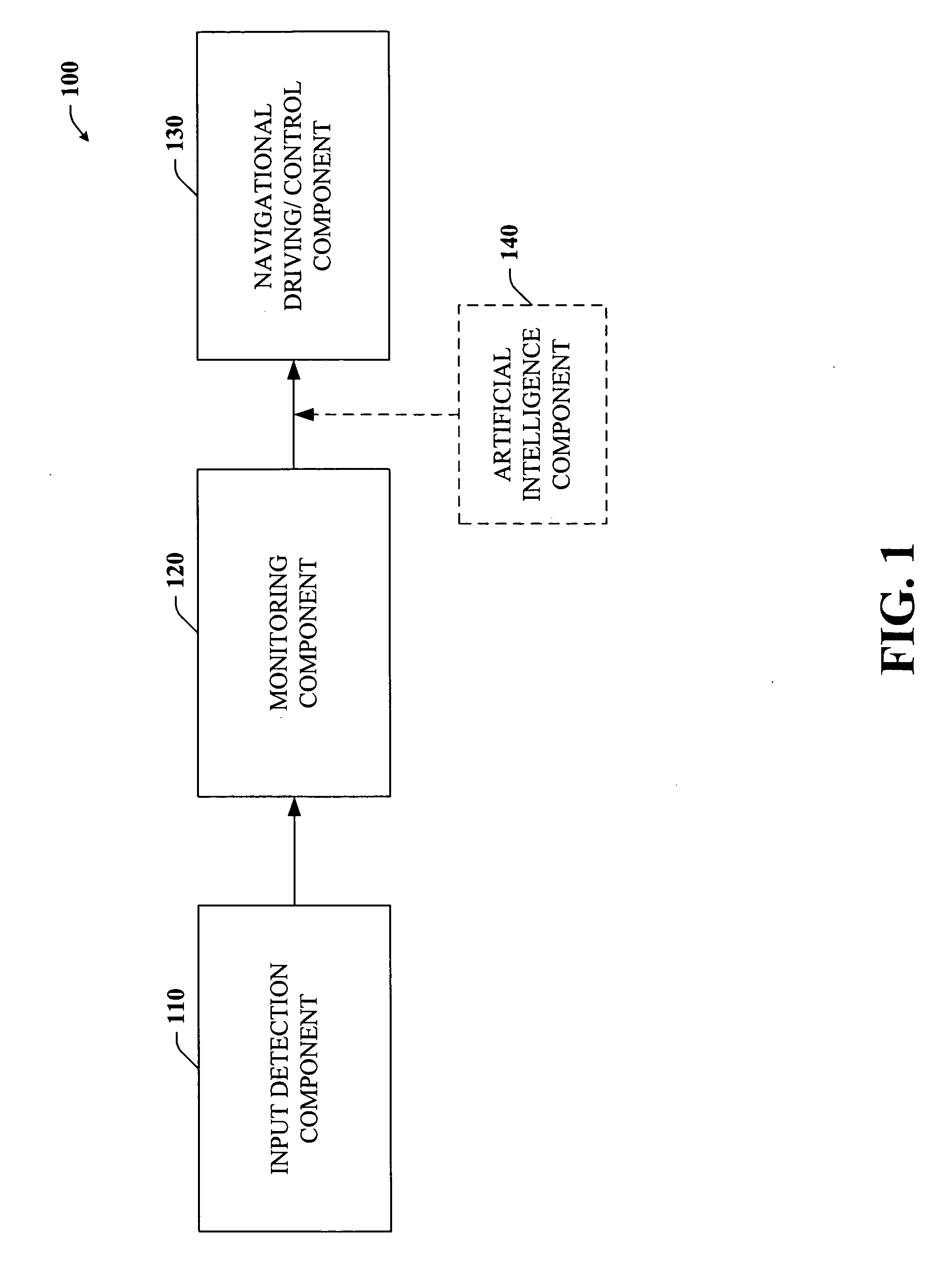
Disclosed is a unique system and method that facilitates cursor control based in part on computer vision activated by a capacitive touch sensor. When turned on, user hand gestures or movements can be tracked by a monitoring component and those movements can be converted in real-time to control or drive cursor movements and / or position on a user interface. The system comprises a monitoring component or camera that can be activated by touch or pressure applied to a capacitive touch sensor. A circuit within the sensor determines when the user is touching a button (e.g., on keyboard or mouse) that activates the monitoring component and cursor control mechanism. Thus, intentional hand movements by the user can readily be determined.

Description

TECHNICAL FIELD [0001] The present invention relates generally to navigating in a two-dimensional space and in particular, to tracking hand motion and navigating through the two-dimensional space according to such hand motion. BACKGROUND OF THE INVENTION [0002] In the last decade, computer usage has increased exponentially. Such significant increases have given rise to a vast amount of new computing technologies that facilitate such activities as making telephone calls, video gaming between different computer users, publishing, and conducting business meetings. In addition, computer shapes and sizes have gone from large and bulky to smaller and sleeker designs. Some are in tablet-form or hand-held dimensions that allow data input via voice and / or hand-writing recognition. Thus, the overall computing experience continues to advance as consumers become more demanding and as their needs evolve. [0003] More recently, further developments continue in the area of navigating through conten...

Claims


Application Information

Patent Timeline
IPC IPC(8): G09G5/00
CPCG06F1/1616G06F1/1686G06F1/169G06F3/04883G06F3/0425G06F3/044G06F3/0416G06F2203/04106G06F3/04166
Inventor WILSON, ANDREW D.
Owner MICROSOFT TECH LICENSING LLC
Learn More