Method and apparatus for generating compressed stencil test information

a stencil and information technology, applied in the field of graphics rendering, can solve the problems of affecting the efficiency of the video graphics system, and potentially overlapping of objects

Active Publication Date: 2006-02-16
ATI TECH INC
View PDF7 Cites 34 Cited by
  • Summary
  • Abstract
  • Description
  • Claims
  • Application Information

AI Technical Summary

Problems solved by technology

When more than one object is to be displayed on a visual output, the objects may potentially overlap and the graphics processing may include unnecessary steps due to pixel information being calculated for an occluded object.
As the calculation of such pixel information is unnecessary, it adversely affects the efficiency of the video graphics system.
If, however, the object has a substantially overlapping portion, then the number of unnecessary calculations increases and the efficiency of the video graphics circuit are adversely affected.
Another inefficiency arises when a stencil buffer is used during the render of an output image.
Pixels that fall within the shadow are not visible and therefore may be unnecessarily rendered.
Therefore, since the stencil may block out all pixels in the same x,y address, for example, such as hidden by the shadow, it is inefficient to render the pixels which are not visible due to the shadow and / or depth occlusion.
On this final pass, it is inefficient to process those pixels whose stencil value is 0, as they will ultimately not be written.
Therefore, it can be determined if a pixel will fail a greater-than depth test but it cannot be determined if a pixel will fail or pass a less-than or equal-to depth comparison.
Therefore, the hierarchical z determination must be turned off from many operations, providing an inefficient graphics processing system.
One problem with existing hierarchical depth tests is that the minimum value of a tile is compared to the z range of the entire primitive.
Therefore, inefficiencies exist based on system settings of primitives with regard to settings for number of pixels within a tile.
Furthermore, tiles may be too large to allow an accurate minimum z value and the number of bits used to store the minimum z value may be insufficient.
These above-noted limitations may result in pixels passing the hierarchical z test and being shaded, wherein these pixels are then later culled by depth and stencil tests.

Method used


Image

  • Method and apparatus for generating compressed stencil test information
  • Method and apparatus for generating compressed stencil test information
  • Method and apparatus for generating compressed stencil test information

Examples


Embodiment Construction

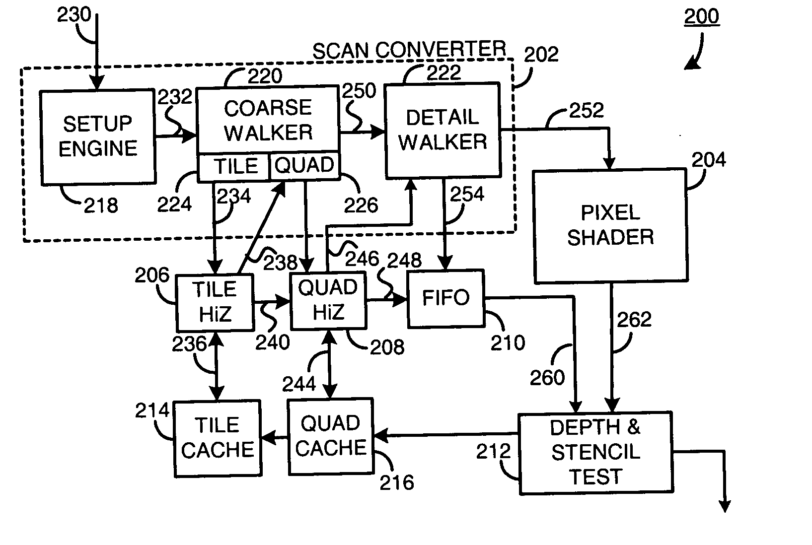
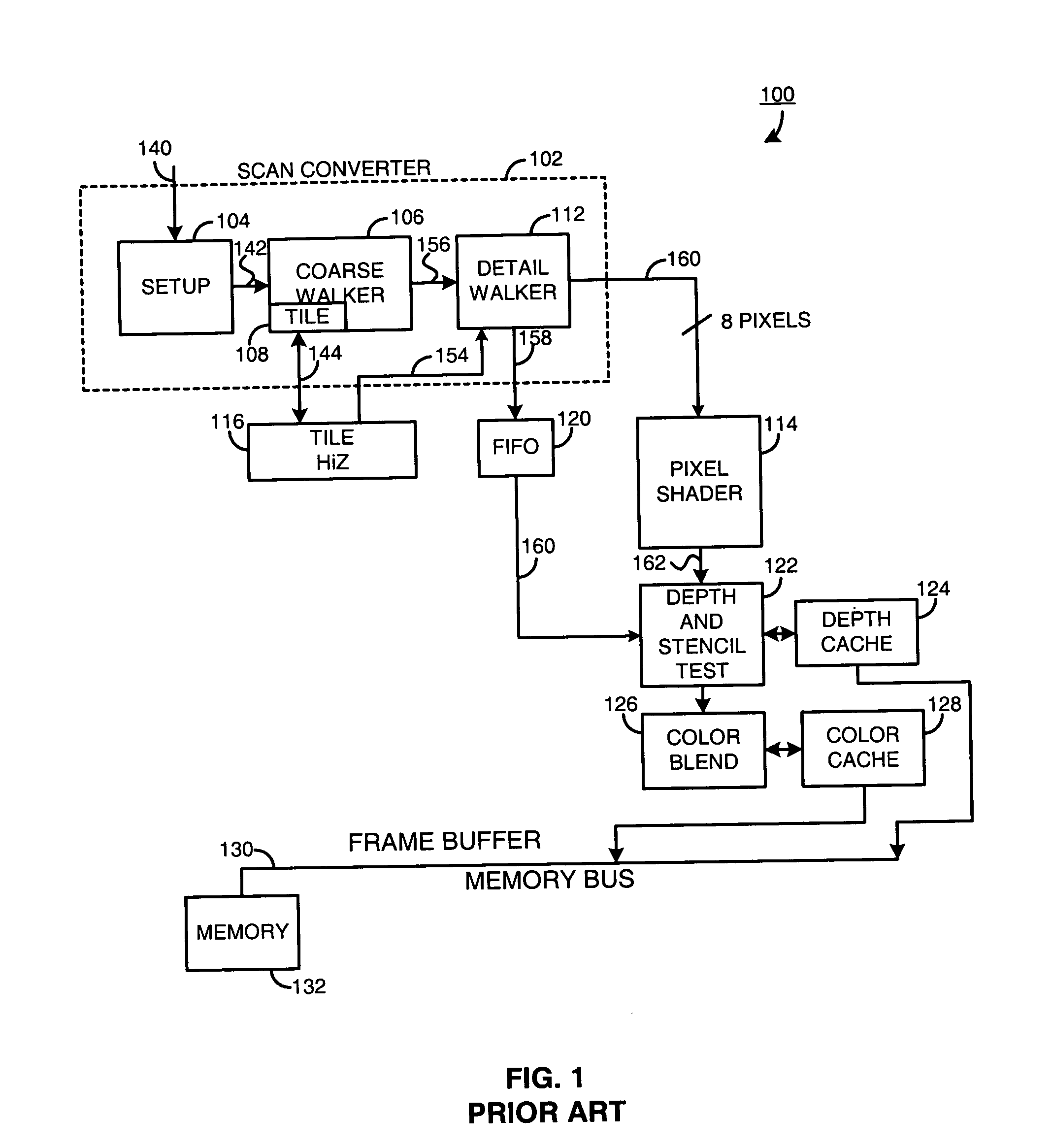
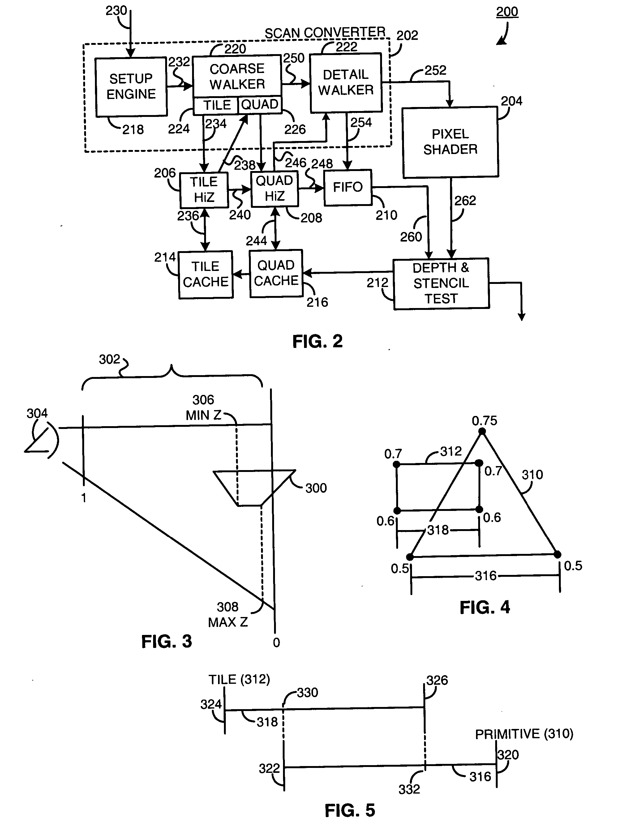
[0023] Generally, a method and apparatus for generating hierarchical depth culling characteristics includes determining a first minimum depth value and a first maximum depth value for a first graphical element. A first graphical element may be a primitive, such as a triangle, rectangle or any other graphical element having a plurality of vertices. The first minimum depth value may be the minimum z-plane depth of a pixel within the primitive, first graphical element and the first maximum depth value is a maximum z-plane value for a pixel within the primitive, first graphical element.

[0024] The method and apparatus further includes determining a second minimum depth value and a second maximum depth value for a second graphical element. The second graphical element may be a tile including a plurality of pixels. The second minimum depth value is a minimum z-plane value of the pixels within the second graphical element, the tile, and the second maximum depth value is a maximum z-plane v...


PUM


Abstract

A method for rendering pixels for display includes generating stencil values on a per pixel basis for storage in stencil buffer memory; selecting a group of stencil values that represent a block of pixels; generating compressed stencil data associated with the group of stencil values; and performing stencil testing on a corresponding incoming block of pixels using the compressed stencil data.

Description

RELATED CO-PENDING APPLICATION [0001] This is a continuation-in-part of U.S. patent application entitled METHOD AND APPARATUS FOR GENERATING HIERARCHICAL DEPTH CULLING CHARACTERISTICS, having Ser. No. ______, having attorney docket number 00100.______ filed on Aug. 10, 2004, having as inventors Larry D. Seiler et al. and owned by instant Assignee.FIELD OF THE INVENTION [0002] The present invention relates generally to graphics rendering and more particularly to comparing pixel values prior to graphics rendering. BACKGROUND OF THE INVENTION [0003] Video graphics circuit generates pixel information for objects to be displayed on a computer screen, monitor or television. The source for the object may be a television broadcast, a cable television transmission, satellite transmission, computer generated program, a web-based image generator, or any other suitable image generation source. For computer screens, video graphics circuits partition each of the objects to be displayed into primi...

Claims


Application Information

Patent Timeline
Patent Type & Authority Applications(United States)
IPC IPC(8): G06T1/00G06F15/00G06T15/40
CPCG06T15/005
Inventor MOREIN, STEPHEN L.
Owner ATI TECH INC
Why Eureka
Try Eureka