Hand recognition system

a recognition system and hand technology, applied in static indicating devices, instruments, computer security arrangements, etc., can solve the problems of affecting the performance of each of these biometric devices, and affecting the accuracy of hand recognition

Inactive Publication Date: 2006-02-16
PLANAR SYSTEMS
View PDF47 Cites 174 Cited by
  • Summary
  • Abstract
  • Description
  • Claims
  • Application Information

AI Technical Summary

Problems solved by technology

One of the problems with these types of systems is that access is provided to any key holder, and the keys are transferable and easily lost, stolen or passed on.
Each of these biometric devices have performance limitations because the characteristic of the person that is measured tends to vary greatly even for a given individual.
For example, a person's fingerprints suffer day-to-day damage from scratches, abrasions and so on, that make accurate automatic identification very difficult.
Also, biometric devices tend to be very costly to manufacture because of the precision required for r

Method used


Image

  • Hand recognition system
  • Hand recognition system
  • Hand recognition system

Examples


Embodiment Construction

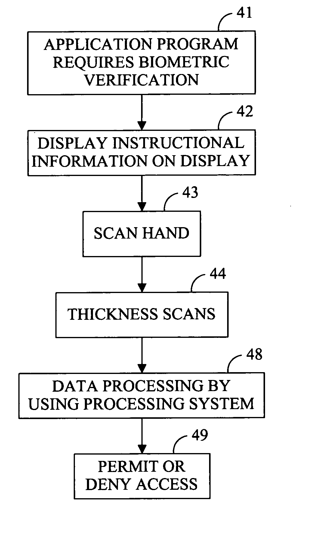
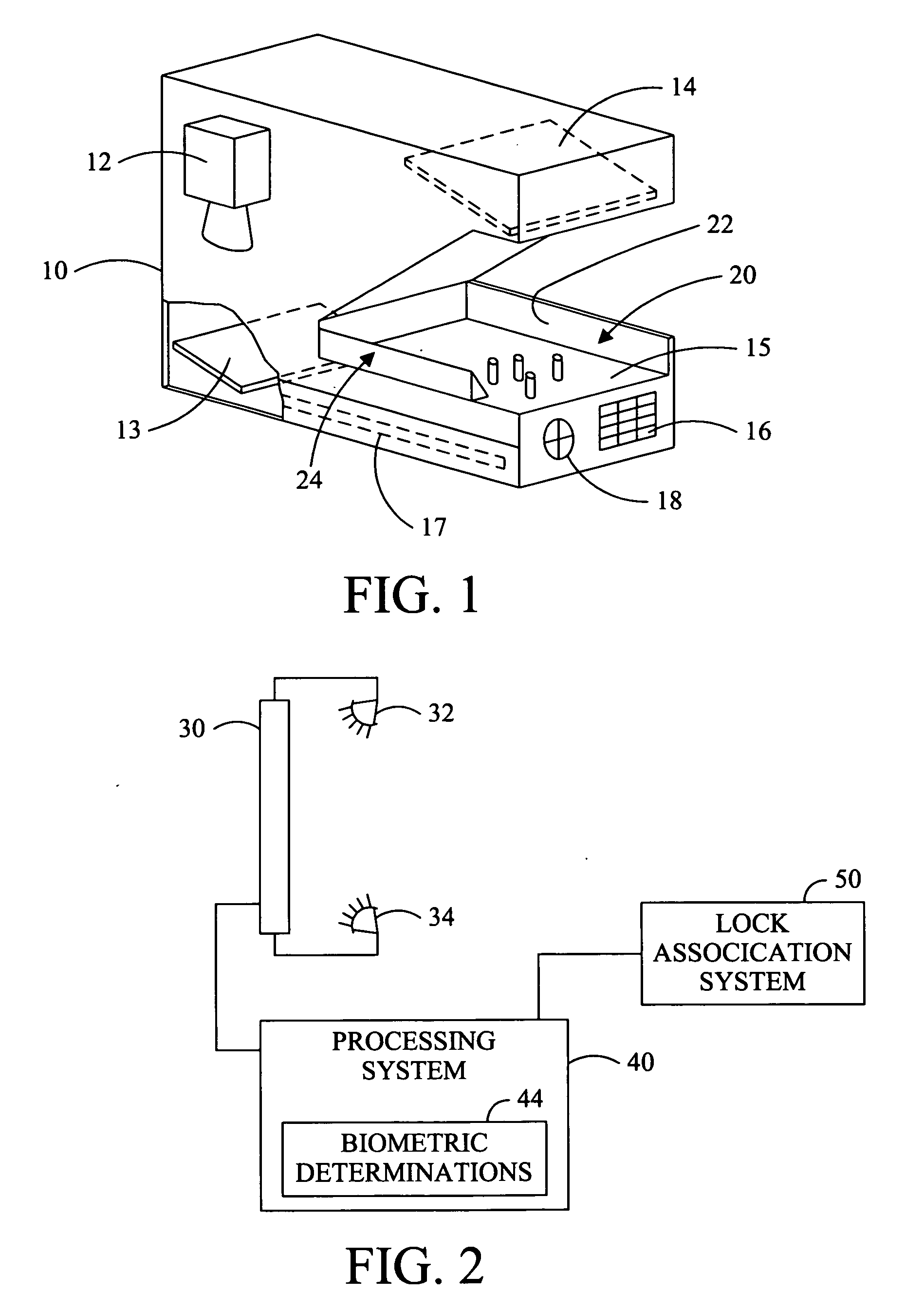
[0031] The present inventors considered the aforementioned hand recognition imaging systems and came to the realization that a non-intrusive hand recognition system may include a display, which is capable of displaying still images and / or video images, together with integrated light sensitive elements to detect the presence of the hand of the user, and / or the characteristics of the hand, and / or the shape of the hand, etc., described later. The hand may include any portion of the hand, such as for example, the fingers (e.g., 1-4), the thumb, the palm, lines on the hand, webbing between fingers, knuckle positions, and translucency.

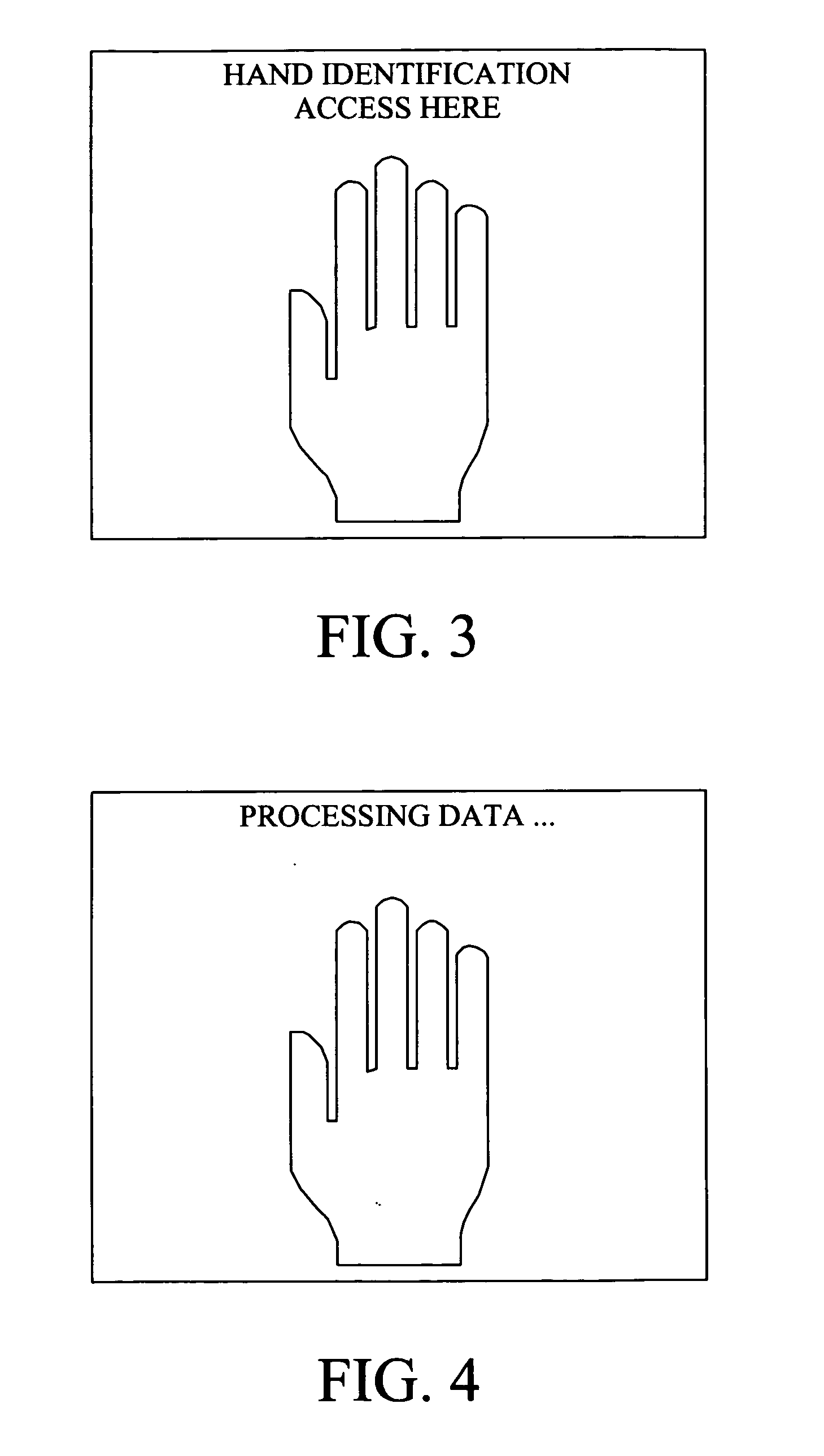
[0032] Referring to FIG. 2, the display 30 may be mounted to a wall, sit on a desktop, or any other suitable place. In addition to being used for hand recognition, the display 30 may be used to present text and / or images, such as information regarding use of the hand recognition system, responses to using the hand recognition system, context-relevant inform...


PUM


Abstract

A hand recognition system.

Description

BACKGROUND OF THE INVENTION [0001] The present invention relates to verification devices. More particularly, it relates to a verification system which measures the hand of a user for the purposes of verification. [0002] Traditionally, keys of both a mechanical and an electrical nature have been used to restrict access to secure areas to authorized individuals. The controlled access to secure areas may be to physical areas, such as with the common lock and key, or to information, such as with computer terminal passwords, or to valuables, such as with automatic bank teller personal identification codes. One of the problems with these types of systems is that access is provided to any key holder, and the keys are transferable and easily lost, stolen or passed on. [0003] More recently, identification devices relying upon biometric characteristics unique to an individual have been proposed. Such biometric devices measure and compare characteristics of such things as voice, fingerprints, ...

Claims


Application Information

Patent Timeline
IPC IPC(8): G06K9/00G06F1/16G06F21/00G09G3/36
CPCG06F1/1601G06F21/32G09G3/3648G06K9/00362G06F2200/1612G06V40/10
Inventor SIEGEL, ROYBOER, WILLEM DENABILEAH, ADIEL
Owner PLANAR SYSTEMS
Why Eureka
Try Eureka