
Insertion guide for a spinal implant

a technology insertion guide, which is applied in the field of spinal disc arthroplasty apparatus and methods, can solve problems such as the dislocation of the two vertebra

Inactive Publication Date: 2006-02-16
STRYKER SPINE
View PDF87 Cites 132 Cited by
  • Summary
  • Abstract
  • Description
  • Claims
  • Application Information

AI Technical Summary

Benefits of technology

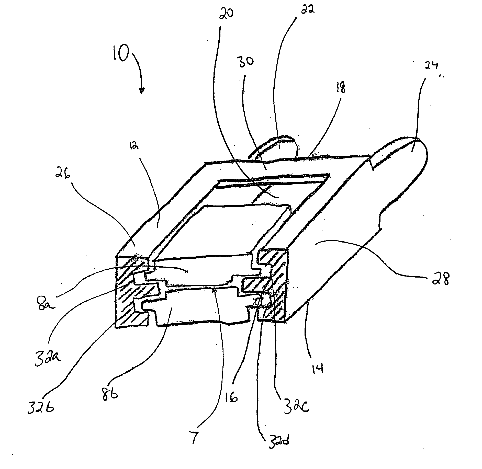
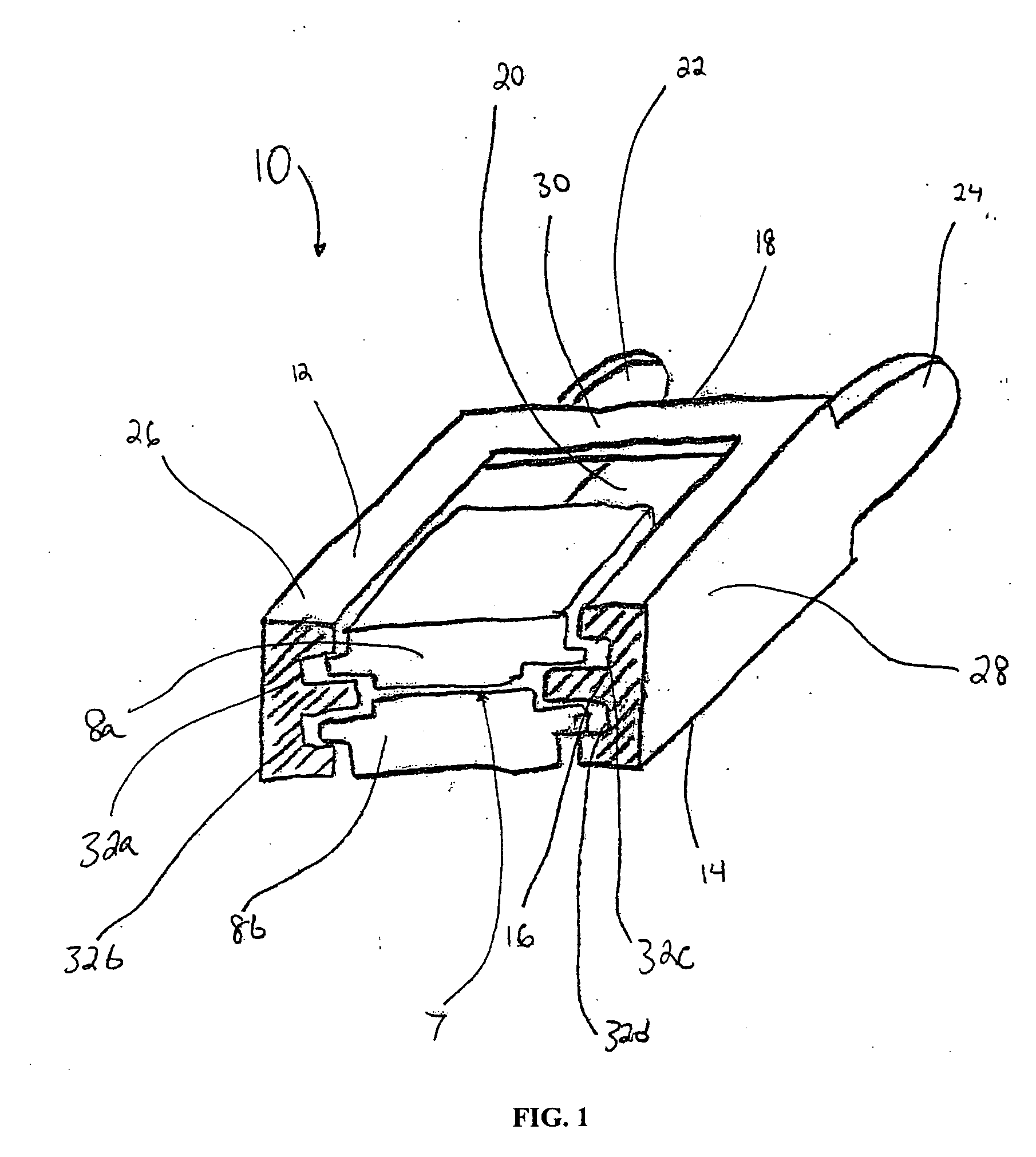
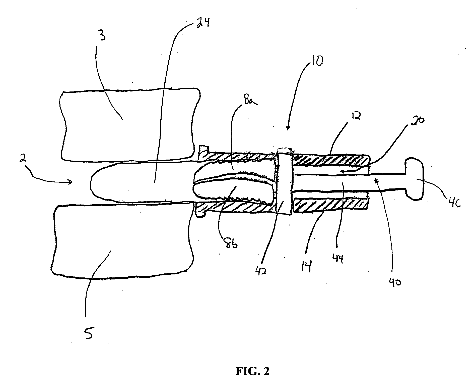
[0006] In one preferred embodiment of the present invention, a spinal implant insertion guide includes at least one channel adapted for receiving and facilitating movement of at least two cooperating pieces of a spinal implant and a portion suitable for insertion into the intervertebral space between two vertebrae. The portion suitable for insertion into the intervertebral space is a projecting portion having a sloped height and a rounded end. This shape allows the portion to be easily inserted between the two vertebrae. After the projecting portion has been inserted between two vertebrae, the channel desirably extends into the intervertebral space, thereby allowing the implant to be implanted therein. The two pieces of the spinal implant may remain in cooperation with each other throughout movement in the at least one channel, however, slight movement of the pieces may be possible. There may be several embodiments relating to this aspect of the invention. For example, the channel may further include slots for positioning the pieces of the spinal implant in cooperation with one another. The insertion guide according to this embodiment of the present invention may also include a plunger for facilitating the movement of the spinal implant pieces. The portion suitable for insertion into the intervertebral space between two vertebrae may cause distraction of the two vertebrae upon insertion. In certain embodiments, the insertion guide may be packaged with the spinal implant preloaded therein. In other preferred embodiments, the spinal implant may be loaded into the insertion guide immediately before a surgical procedure. The insertion guide may be constructed of a broad range of biocompatible materials such as stainless steel. In certain preferred embodiments, the insertion guide is made of a polymeric material, thereby making it relatively inexpensive to construct and disposable.
[0010] In another preferred embodiment of the present invention, a method of inserting an at least two piece spinal implant includes providing an insertion guide having at least one channel, inserting at least a portion of the insertion guide into an intervertebral space between two vertebrae, placing the at least two piece spinal implant into the at least one channel such that the spinal implant pieces cooperate with one another, and moving the spinal implant pieces together into the intervertebral space. The implant pieces preferably remain in cooperation throughout their insertion. The method according to this aspect of the present invention may also include distracting the vertebrae and / or preparing the vertebrae for receiving the spinal implant. The method may also include stabilizing the guide with respect to the vertebrae, with or without an external support. Finally, this method may also include providing and utilizing a plunger for facilitating the movement of the implant.
[0013] A preferred method in accordance with the present invention may be a method of inserting a multi-piece spinal implant. This method may include the steps of providing an insertion guide defined by a channel having at least two slots therein, inserting at least a portion of the insertion guide into an intervertebral space between two vertebrae, placing each piece of the multi-piece spinal implant into the channel such that each implant piece engages at least one slot and the spinal implant pieces cooperate with on another, and moving the spinal implant pieces into the intervertebral space while maintaining the spinal implant pieces in cooperation with one another and allowing slight movement of the spinal implant pieces with respect to each other.
[0015] Yet another preferred multi-piece spinal implant insertion guide in accordance with the present invention may include a channel including at least two slots, each of the at least two slots capable of engaging a different portion of a multi-piece spinal implant, at least one extension suitable for insertion into an intervertebral space, and a plunger for facilitating movement of the spinal implant pieces. Preferably, the guide should be configured so that the pieces of the multi-piece spinal implant remain in cooperation throughout movement in the channel and are capable of slight movement with respect to each other.

Problems solved by technology

The portion suitable for insertion into the intervertebral space between two vertebrae may cause distraction of the two vertebrae upon insertion.

Method used


Image

  • Insertion guide for a spinal implant
  • Insertion guide for a spinal implant
  • Insertion guide for a spinal implant

Examples


Embodiment Construction

[0023] In describing the preferred embodiments of the subject matter illustrated and to be described with respect to the drawings, specific terminology will be used for the sake of clarity. However, the invention is not intended to be limited to the specific terminology and includes all technical equivalence which operates in a similar manner to accomplish a similar purpose.

[0024] Referring to the drawings, wherein like reference numerals represent like elements, there is shown in FIGS. 1-3, in accordance with an embodiment of the present invention, an insertion guide for a spinal implant designated generally by reference numeral 10. In the preferred embodiment shown in the figures, insertion guide 10 is designed to be used in aiding in the insertion of a spinal implant 7. As best shown in FIG. 1, insertion guide 10 is of unitary construction having a top side 12, a bottom side 14, a proximal end 16, and a distal end 18. Guide 10 also includes a channel 20 adapted to receive a spin...


PUM


Abstract

A spinal implant insertion guide is disclosed. The insertion guide includes at least one channel suitable for receiving and facilitating movement of a spinal implant into an intervertebral space between two vertebrae and a portion suitable for insertion into the intervertebral space. In embodiments for use with spinal implant having multiple pieces, the pieces of the spinal implant remain in cooperation throughout movement. The guide may further include a plunger for facilitating the movement of the spinal implant.

Description

CROSS-REFERENCE TO RELATED APPLICATIONS [0001] his application claims the benefit of the filing date of U.S. Provisional Patent Application No. 60 / 601,461 filed Aug. 13, 2004, the disclosure of which is hereby incorporated herein by referenceBACKGROUND OF THE INVENTION [0002] The present invention relates generally to apparatus and methods for use in spinal disc arthroplasty, and more particularly, to apparatus and methods for use in the insertion of disc replacement implants into the intervertebral space between two adjacent vertebrae. [0003] Whether due to injury, wear, or genetic defect, intervertebral disc degeneration is a problem suffered by many people. Typically, this spinal problem has been addressed by removing the disc material and replacing it with a spinal implant which fuses two adjacent vertebrae. Recently, however, there has been a significant amount of activity directed toward filling the intervertebral space with spinal implants that permit relatively natural movem...

Claims


Application Information

Patent Timeline
IPC IPC(8): A61F2/34
CPCA61B2017/0256A61F2/4425A61F2/4611A61F2220/0025A61F2002/30601A61F2002/30616A61F2002/4627A61F2002/30387
Inventor MCDONNELL, CHRISTOPHER
Owner STRYKER SPINE
Learn More