Lead assembly and methods including a push tube

a technology of push tube and lead, which is applied in the direction of internal electrodes, transvascular endocardial electrodes, therapy, etc., can solve the problems of further complicated procedures, difficult to push the lead through the twisting vasculature with a stylet, and difficult to navigate flexible cardiac, etc., to achieve less invasive, easier to navigate the vasculature, and small cross-section

Inactive Publication Date: 2006-02-16
CARDIAC PACEMAKERS INC
View PDF21 Cites 68 Cited by
  • Summary
  • Abstract
  • Description
  • Claims
  • Application Information

AI Technical Summary

Benefits of technology

[0012] The above described assembly allows for implantation of slender leads through tortuous vasculature (e.g. coronary veins around the left side of the heart) using a push tube. In one option, the lead assembly includes a distal tip sized and shaped to couple with a push tube that extends along at least a portion of the elongate body. A pushing force is applied to the push tube and transmitted to the distal tip to push the distal end of the elongate body through vasculature and into or around the heart (e.g., into the epicardium of the heart). A portion of the elongate body proximal to the distal tip and coupled thereto is pulled as the distal tip is pushed by the push tube. In another option, the distal tip includes a seat. The push tube and the seat include, optionally, non-circular perimeters or a key and a recess. The push tube is rotated to correspondingly rotate the distal tip into a desired orientation for optimum electrode to tissue contact, in one option. In another option, the push tube is rotated to turn the distal tip and the elongate body and allow for easier navigation of the vasculature.
[0013] Because the push tube is fed over the guide wire or over the elongate body, a stylet lumen or the like is not necessary. In one option, the elongate body has a smaller cross-section and is less invasive than leads having a stylet lumen. The lead assembly includes additional conductors or the like in the space occupied by a stylet lumen, in another option. The conductors of the lead assembly described herein include cables that extend substantially linearly along the elongate body because a stylet lumen formed with coiled conductors is not necessary. Linear cables take up less space within the elongate body, as compared to coiled conductors, and allow for a lead assembly with a smaller outer perimeter that also has multiple conductors and corresponding electrodes. In yet another option, a lumen is formed within the elongate body and is sized and shaped to receive the push tube and the guide wire and the push tube is fed over the guide wire to navigate the elongate body through vasculature. Having a push tube lumen within the elongate body decreases the profile of the elongate body allowing for easier navigation of the lead assembly. Additionally, the push tube provides increased column strength compared to a stylet and facilitates transmission of increased pushing forces to the distal end of the elongate body.
[0014] Moreover, the push tube of the assembly allows for the positioning of a variety of active fixation devices into desired orientations along the elongate body, for instance, after the elongate body is positioned within vasculature and / or a heart. The elongate body tracks through the vasculature easily without the active fixation devices disposed along the elongate body until after implantation of the elongate body. In one option, the active fixation devices have a larger profile than the elongate body and are introduced after the elongate body is positioned as desired within a heart and / or the vasculature. In another option, when the active fixation device and distal tip are coupled the combined outer perimeter engages the surrounding vasculature of, for example, a vein or artery, and securely couples the elongate body with the vasculature. In another option, active fixation devices sized and shaped to deform the elongate body are advanced along the elongate body. In one option, the active fixation devices deform and push the elongate body (e.g. including electrodes) into snug engagement with the vasculature. In another option, active fixation devices are actuated with the push tube (e.g. by rotating the push tube to turn a threaded fixation device) to couple with surfaces within the vasculature or on the epicardial surfaces of a heart.

Problems solved by technology

It is often difficult to navigate flexible cardiac leads through tortuous vasculature for implantation within the vasculature or the heart.
The deformable nature of some leads makes it difficult to push the lead through the twisting vasculature with a stylet.
The procedures are further complicated by enlarging the outer perimeter of leads to accommodate stylet lumens.
Navigation of larger leads is complicated especially in tortuous vasculature, such as around the left side of the heart.
The fixation features of the lead are one disadvantage of this arrangement.
Navigating the lead through vasculature, such as around the left side of the heart is difficult because the fixation features can undesirably lodge in vasculature tissue prior to reaching the desired implantation location.
With the use of an introducing catheter around the entire arrangement the pusher wire is constrained from bowing to some extent, however the introducer catheter undesirably increases the outer perimeter of the apparatus and complicates navigation of the lead through vasculature.
One disadvantage of this arrangement is the elongated lead body is enlarged to accommodate the stylet.
The lumen and the wound coil increase the outer perimeter of the lead and navigation of the larger lead is complicated within tortuous vasculature.
A disadvantage of this arrangement is that a coil has a relatively thick profile that is difficult to navigate through tortuous vasculature.
Additionally, the coil is not securely engaged to the lead to permit rotation of the coil along with the lead to enhance contact with a desired surface within the vasculature (e.g., the myocardium of a heart).

Method used


Image

  • Lead assembly and methods including a push tube
  • Lead assembly and methods including a push tube
  • Lead assembly and methods including a push tube

Examples


Embodiment Construction

[0052] In the following detailed description, reference is made to the accompanying drawings which form a part hereof, and in which is shown by way of illustration specific embodiments in which the invention may be practiced. These embodiments are described in sufficient detail to enable those skilled in the art to practice the invention, and it is to be understood that other embodiments may be utilized and that structural changes may be made without departing from the scope of the present invention. Therefore, the following detailed description is not to be taken in a limiting sense, and the scope of the present invention is defined by the appended claims and their equivalents.

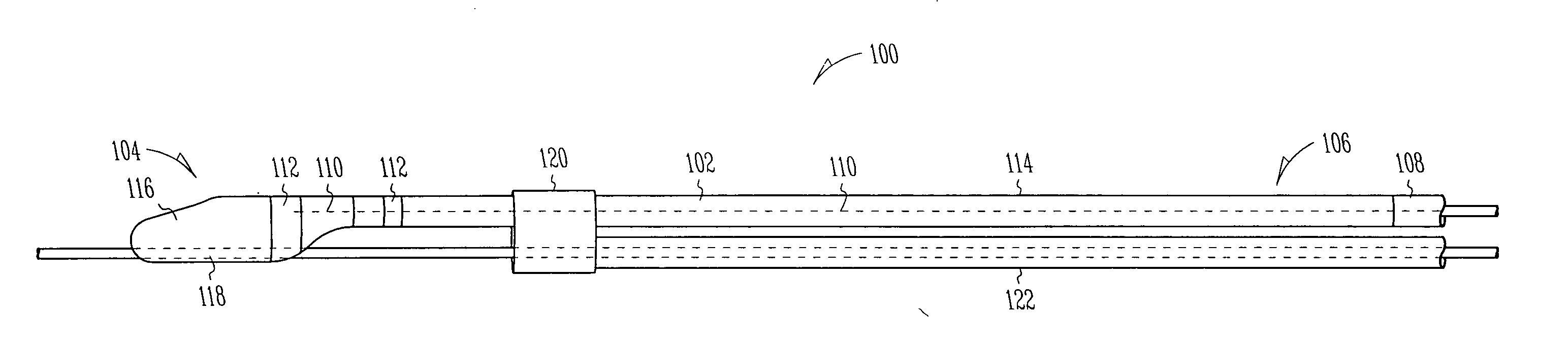
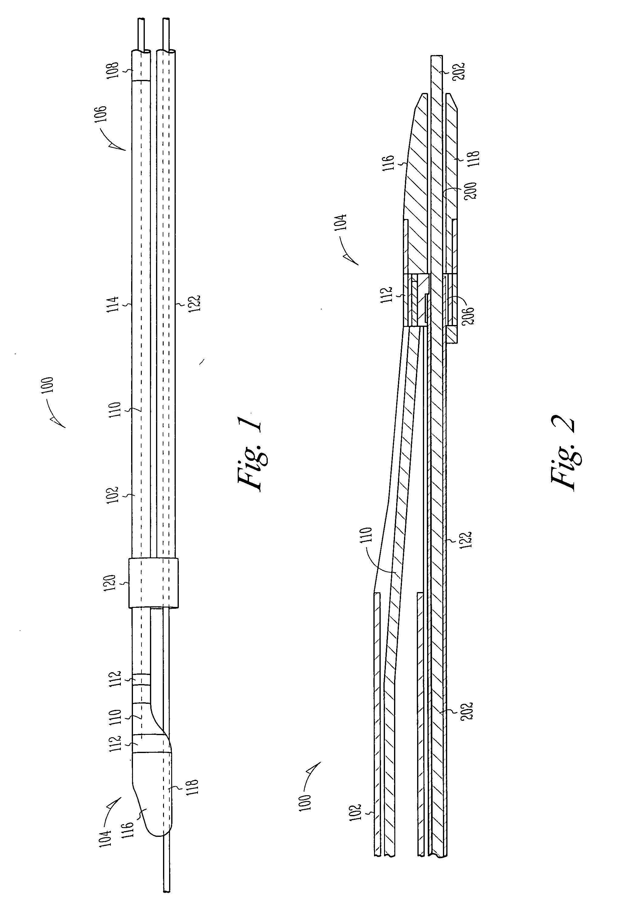
[0053]FIG. 1 is a side view of a lead assembly 100 including an elongate body 102. The elongate body 102 extends between a distal end 104 and a proximal end 106. The elongate body includes a connector terminal 108 at the proximal end 106. The connector terminal 108 is sized and shaped to couple with a pulse ...


PUM


Abstract

A lead assembly includes an elongate body having a conductor electrically coupled with an electrode coupled to the elongate body. The lead assembly includes a push tube extending along at least a portion of the elongate body. A distal tip is coupled to the elongate body substantially adjacent to the distal end of the elongate body. The distal tip is sized and shaped to couple with a push tube distal end. In one option, the distal tip includes a seat to receive the push tube distal end. In another option, the seat is a side rail seat and a guide wire extends along the elongate body and is slidably coupled with the side rail seat. The lead assembly includes, optionally, an active fixation device slidably coupled with a portion of the elongate body, and the active fixation device is sized and shaped to couple with the push tube.

Description

TECHNICAL FIELD [0001] A lead assembly including a push tube and in particular to a lead assembly having a push tube for positioning leads and fixation devices in or around a heart. BACKGROUND [0002] It is often difficult to navigate flexible cardiac leads through tortuous vasculature for implantation within the vasculature or the heart. The deformable nature of some leads makes it difficult to push the lead through the twisting vasculature with a stylet. The leads bend unpredictably and lodge within the veins and arteries. Additionally, leads often include fixation features that snag on the vasculature or provide a larger profile during navigation. Leads with fixation features sometimes require multiple stylets to try navigation of the lead around corners or the like. The procedures are further complicated by enlarging the outer perimeter of leads to accommodate stylet lumens. Such lumens are often defined by coiled conductors that extend through the lead to couple with electrodes....

Claims


Application Information

Patent Timeline
Patent Type & Authority Applications(United States)
IPC IPC(8): A61N1/05
CPCA61N1/056A61N2001/0578A61N1/057
Inventor ZAREMBO, PAUL E.GREENLAND, JOHN
Owner CARDIAC PACEMAKERS INC
Why Eureka
Try Eureka