
Directionless rotary encoder control system for a household appliance

a control system and rotary encoder technology, applied in the direction of program control, domestic stoves or ranges, instruments, etc., can solve the problems of appliance non-functionality, reduced reliability, and only reliable mechanical assemblies and components, and achieve the effect of increasing the first indicia

Active Publication Date: 2006-02-16
E G O ELEKTRO GERAETEBAU GMBH
View PDF13 Cites 39 Cited by
  • Summary
  • Abstract
  • Description
  • Claims
  • Application Information

AI Technical Summary

Benefits of technology

The system enhances user interaction and flexibility in controlling household appliances by allowing any rotational direction to activate and adjust appliance outputs, accommodating different user customs and providing effective feedback, thus improving reliability and functionality beyond mechanical limitations.

Problems solved by technology

However, mechanical assemblies and components are only reliable to a certain extent.
For example, mechanical relays or timers are generally reliable for a certain number of hours of use, but beyond this level, their reliability decreases.
Since failure of a single component often renders the whole appliance non-functional, improving the reliability of the appliance past a certain point is difficult while maintaining costs of the components within certain constraints.
Further, mechanical assemblies and components are designed typically to only perform basic functions.
There is limited flexibility as to what the mechanical assemblies can do and how they can operate.
Implementing new functions or user features is typically not possible with the existing mechanical assemblies.
For example, piezoelectric buzzers are commonly employed in appliances, but the control circuitry is limited, and typically capable of only providing a singe frequency‘beep’ as feedback to the user, typically in regard to notification of an error or an event (timer expiry).
Although the cost of microprocessors have become less expensive, Pearman discloses using a touch screen display and / or a tactile keyboard input which not only significantly increases the cost of the appliance, but may not be desirable from a human design and marketing aspect.

Method used


Image

  • Directionless rotary encoder control system for a household appliance
  • Directionless rotary encoder control system for a household appliance
  • Directionless rotary encoder control system for a household appliance

Examples


Embodiment Construction

[0022] The present invention now will be described more fully hereinafter with reference to the accompanying drawings, in which preferred embodiments of the invention are shown. This invention may, however, be embodied in many different forms and should not be construed as limited to the embodiments set forth herein; rather, these embodiments are provided so that this disclosure will be thorough and complete, and will fully convey the scope of the invention to those skilled in the art. Like numbers refer to like elements throughout.

[0023] Many modifications and other embodiments of the invention will come to mind to one skilled in the art to which this invention pertains having the benefit of the teachings presented in the foregoing descriptions and the associated drawings. Therefore, it is to be understood that the invention is not to be limited to the specific embodiments disclosed and that modifications and other embodiments are intended to be included within the scope of the ap...


PUM


Abstract

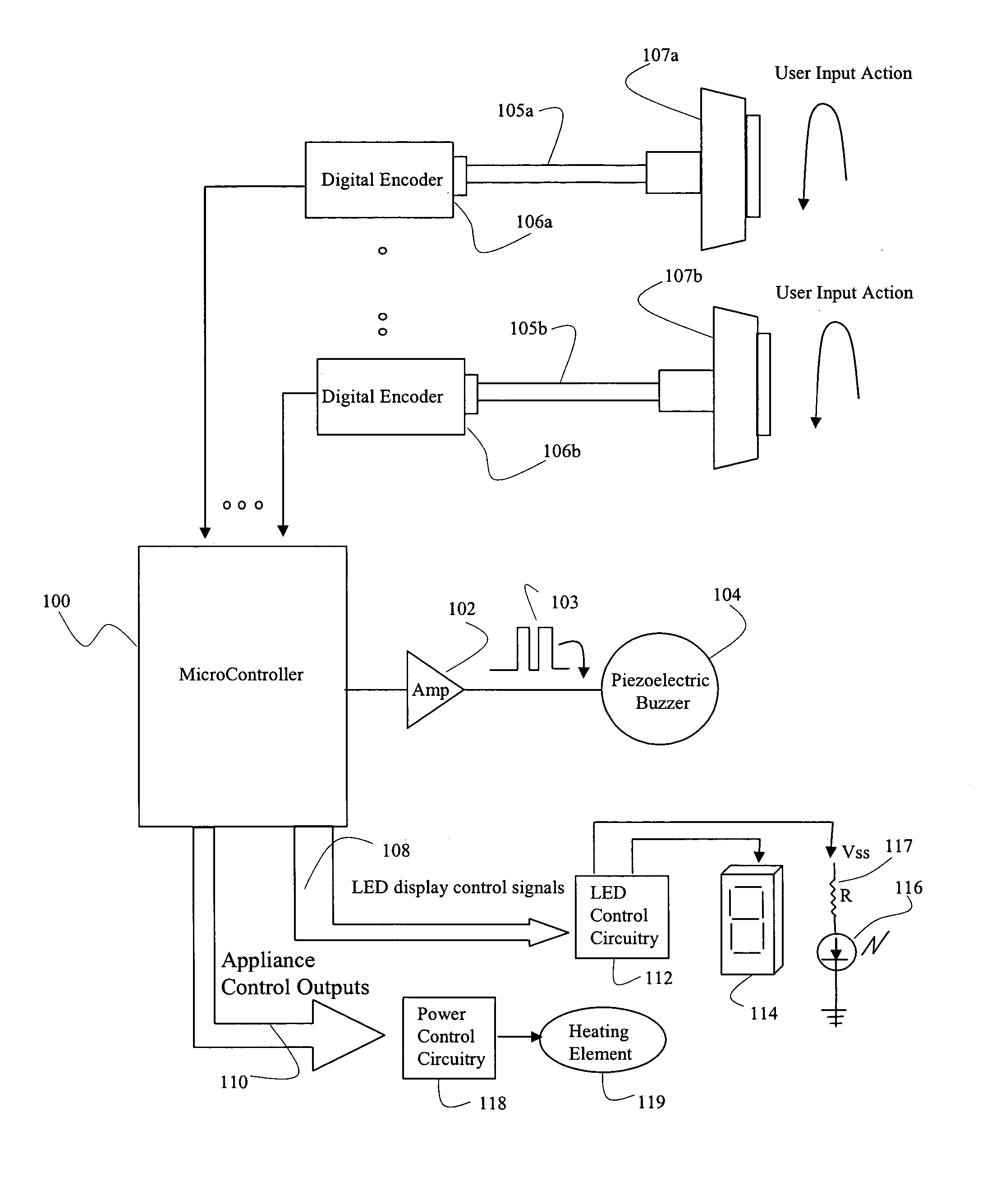
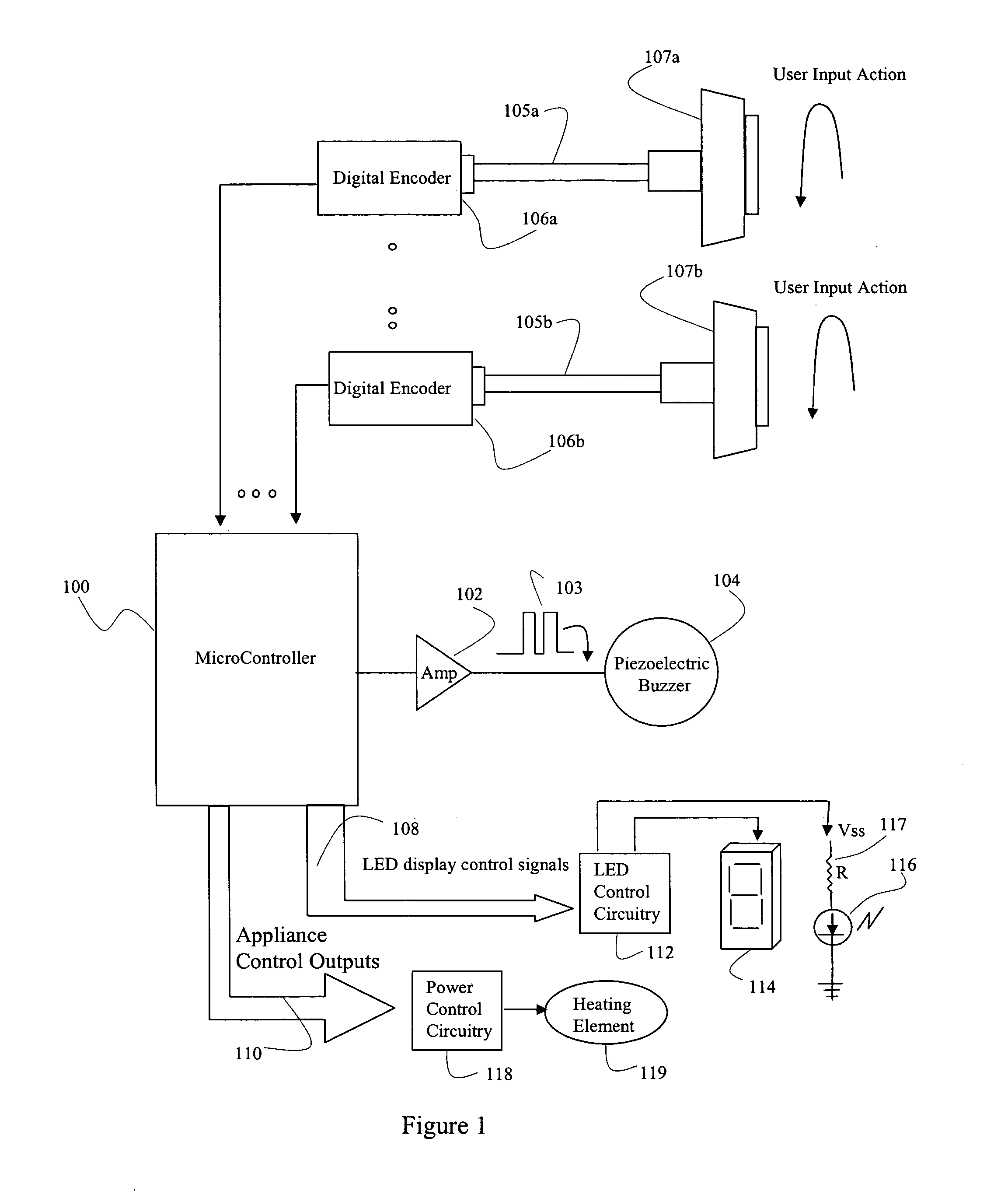
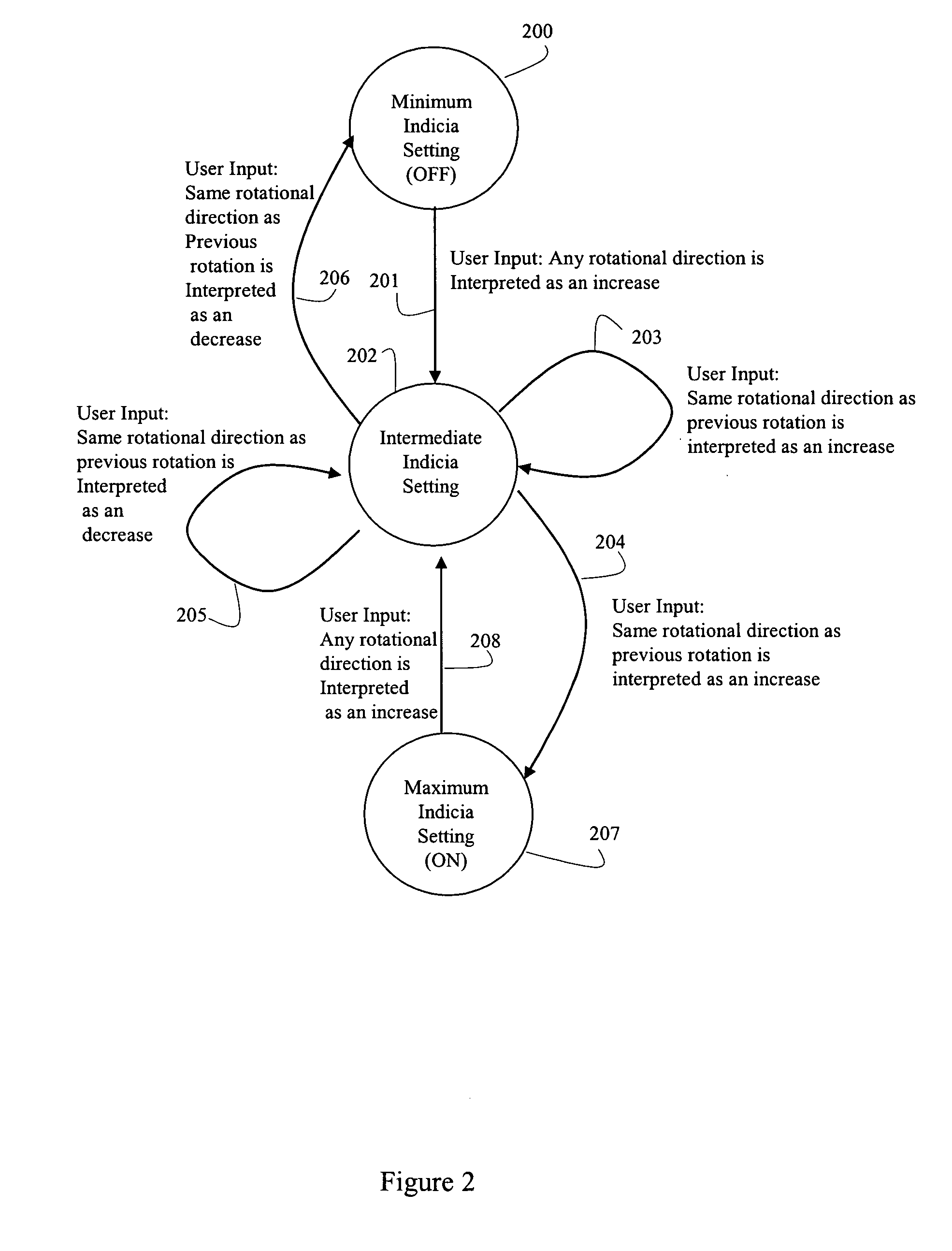
An embodiment of the present invention uses an on-board microcontroller of a household appliance to receive signals from a directionless encoder attached to a knob for receiving user input and processing the signals from the direction encoder according to a control algorithm. The microcontroller may increase the output to an electric heating element on the appliance based on a variety of criteria, including either direction of rotation, current heating element setting, or a change in directional rotation. Alternatively, or in addition, the microcontroller may provide various types of graduated visual or audible feedback to the user.

Description

RELATED APPLICATIONS [0001] This application is a continuation of application Ser. No. ______ filed on ______.FIELD OF THE INVENTION [0002] The present invention relates generally to user control systems for household appliances. More particularly, a directionless rotary encoder is disclosed for receiving user input wherein the encoder is operatively connected to a microcontroller and the microcontroller recognizes either rotational direction of rotation as potentially representing an increasing or decreasing parameter value. The microcontroller may be further configured to control a variable aural or visual output devices providing feedback to the user. BACKGROUND OF THE INVENTION [0003] Traditionally, household appliance controls have been based on mechanical components. Mechanical timers, relays, and solenoids were used to effect various cycles of operation, opening and closing circuits, and actuating mechanical assemblies. Through decades of design and refinement, these controls...

Claims


Application Information

Patent Timeline
Patent Type & Authority Applications(United States)
IPC IPC(8): G05B15/00
CPCG05B19/104G05B2219/23057G05B2219/23023
Inventor HARKCOM, ALTONBRYAN, CRAIG E.CLEMENS, JOERG
Owner E G O ELEKTRO GERAETEBAU GMBH
Learn More