Surface UI for gesture-based interaction

a gesture-based interaction and surface technology, applied in the field of user interface (ui) and display technology, can solve the problems of limited capability of common touch screen technologies, inability to track more, and only handle the applications of today, and achieve the effect of facilitating determination

Inactive Publication Date: 2006-02-16
MICROSOFT TECH LICENSING LLC
View PDF41 Cites 244 Cited by
  • Summary
  • Abstract
  • Description
  • Claims
  • Application Information

AI Technical Summary

Benefits of technology

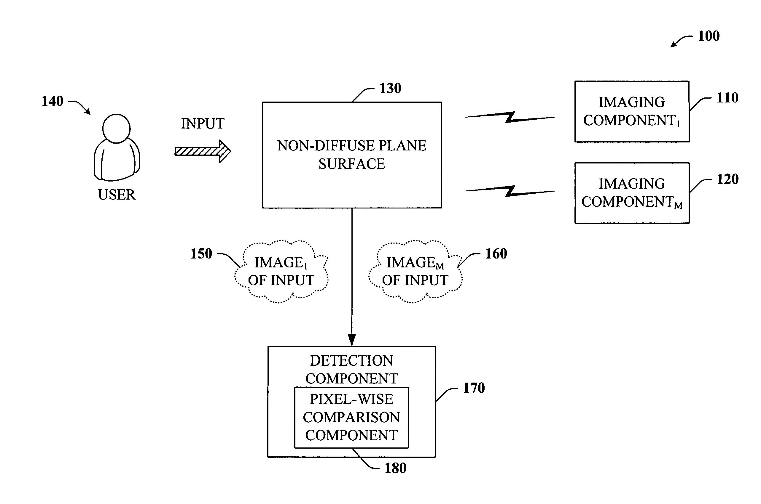
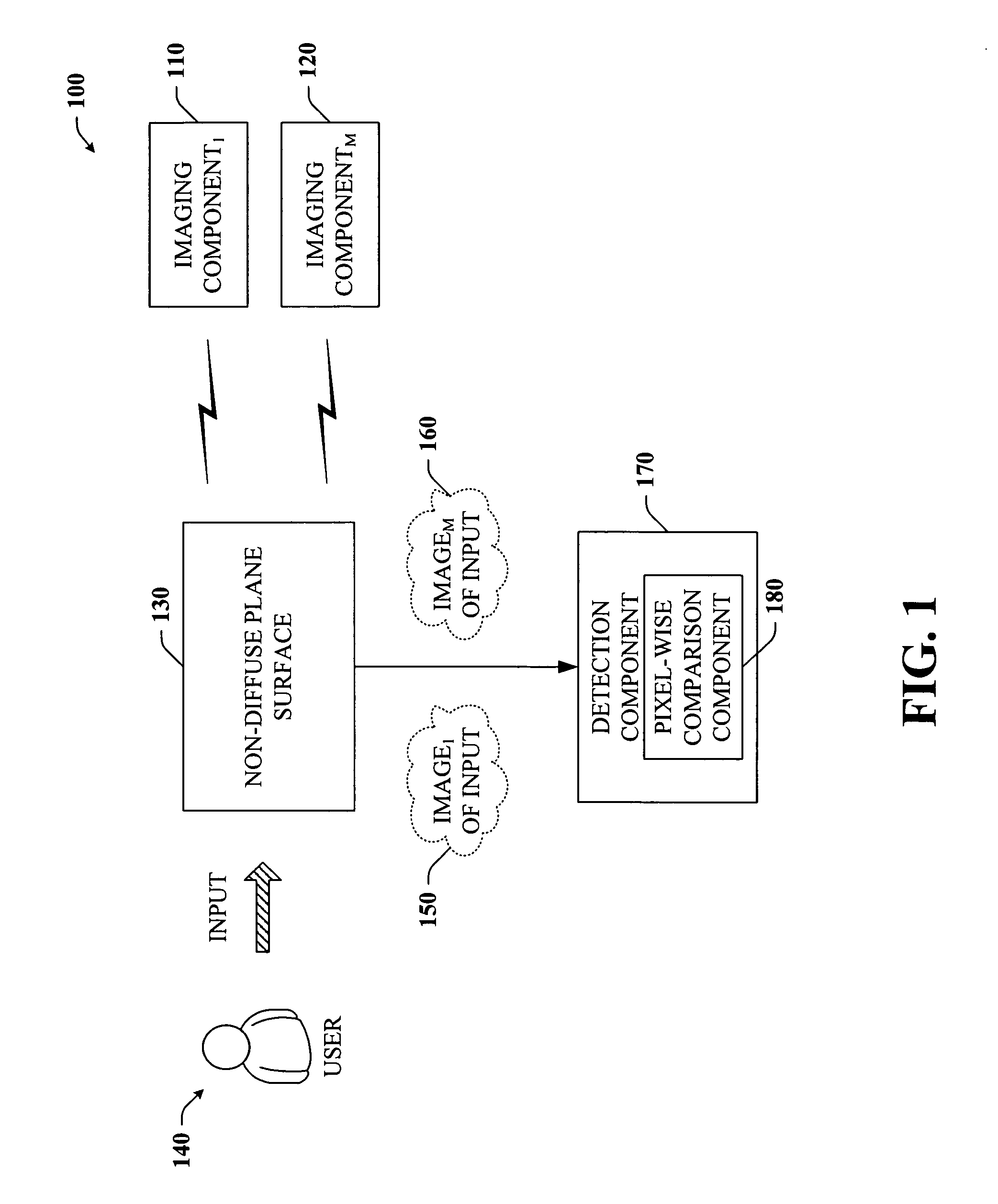
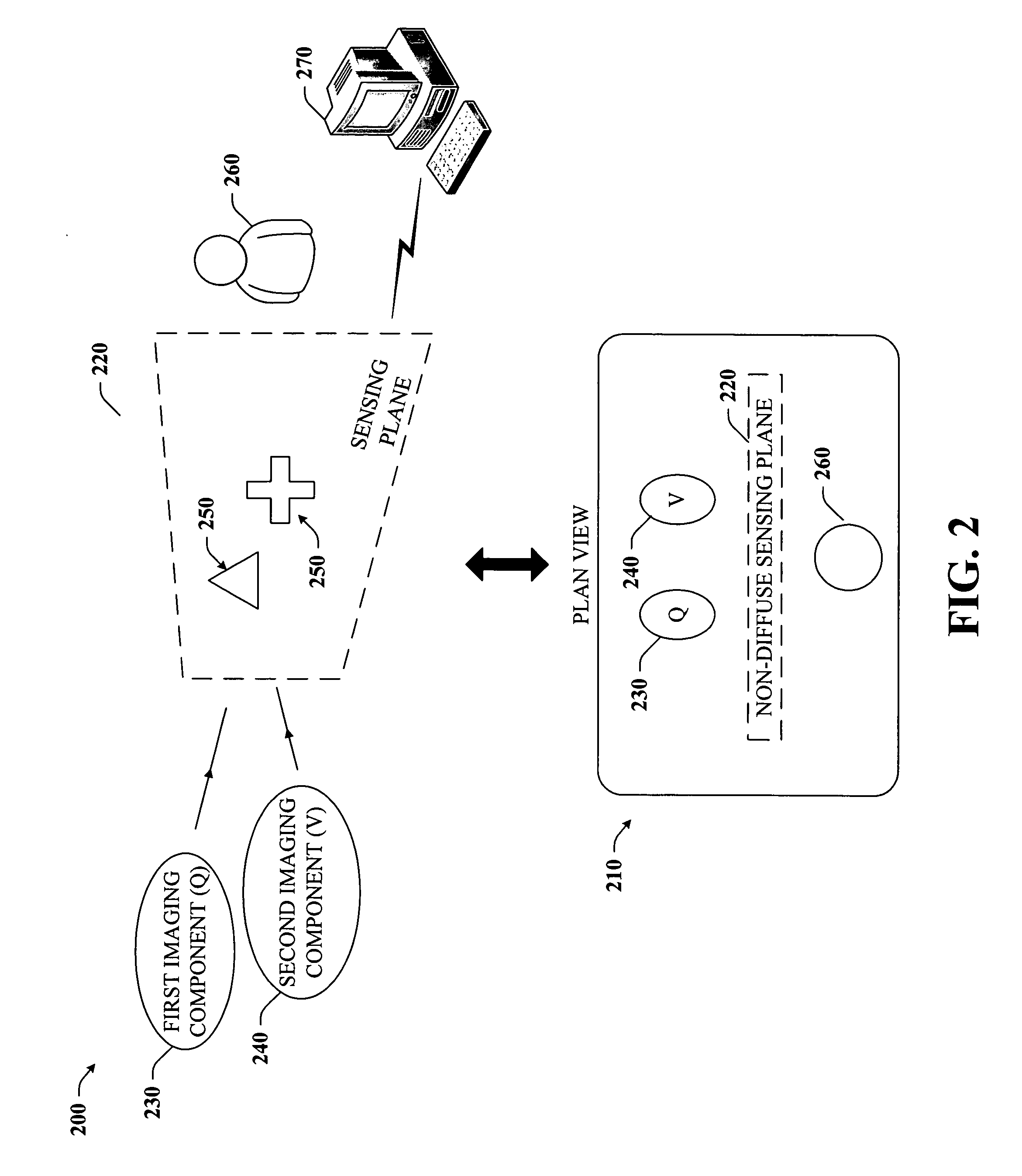
[0008] The present invention relates to a system and method that can compute an image of any objects touching a surface of a plane or display space. More specifically, the systems and methods can facilitate determining which objects in view of the plane exist at a given depth from the plane or display space. This can be accomplished in part by employing a system configuration comprising at least two cameras and a vertical or horizontally located sensing plane or display surface located in front of the cameras. The cameras can be directed toward the plane or display screen / surface. A user interacting with the sensing plane can be positioned on the opposite side of the plane.

Problems solved by technology

Unfortunately common touch screen technologies are limited in capability.
For example, most are not able to track more than a small number of objects on the screen at a time, and typically they report only the two dimensional (2D) position of the object and no shape information.
This can be due in part to superficial limitations of the particular hardware implementation, which in turn are driven by the emphasis on emulating pointer input for common GUI (graphical user interface) interactions.
Typically, today's applications are only able to handle one 2D pointer input.

Method used


Image

  • Surface UI for gesture-based interaction
  • Surface UI for gesture-based interaction
  • Surface UI for gesture-based interaction

Examples


Embodiment Construction

[0033] The present invention is now described with reference to the drawings, wherein like reference numerals are used to refer to like elements throughout. In the following description, for purposes of explanation, numerous specific details are set forth in order to provide a thorough understanding of the present invention. It may be evident, however, that the present invention may be practiced without these specific details. In other instances, well-known structures and devices are shown in block diagram form in order to facilitate describing the present invention.

[0034] As used in this application, the terms “component” and “system” are intended to refer to a computer-related entity, either hardware, a combination of hardware and software, software, or software in execution. For example, a component may be, but is not limited to being, a process running on a processor, a processor, an object, an executable, a thread of execution, a program, and a computer. By way of illustration...


PUM


Abstract

Disclosed is a unique system and method that facilitates gesture-based interaction with a user interface. The system involves an object sensing configured to include a sensing plane vertically or horizontally located between at least two imaging components on one side and a user on the other. The imaging components can acquire input images taken of a view of and through the sensing plane. The images can include objects which are on the sensing plane and / or in the background scene as well as the user as he interacts with the sensing plane. By processing the input images, one output image can be returned which shows the user objects that are in contact with the plane. Thus, objects located at a particular depth can be readily determined. Any other objects located beyond can be “removed” and not seen in the output image.

Description

TECHNICAL FIELD [0001] The present invention relates generally to user interface (UI) and display technology and in particular, to projecting an image onto a plane surface which effectively creates a UI to facilitate gesture-based interaction with such surface. BACKGROUND OF THE INVENTION [0002] In the last few years alone, computing demands have increased dramatically. Such significant increases have given rise to a vast amount of new computing technologies. For example, a keyboard, mouse, or some other pointing (e.g., a stylus) used to be required for data entry as well as data manipulation. However, nowadays, users also have the option to utilize a variety of other means to enter, access, and / or manipulate data displayed on or stored in a computer. One primary example is touch screen technology. In general, a touch screen is an input device that allows users to operate a computer by simply touching the display screen. [0003] Unfortunately common touch screen technologies are limi...

Claims


Application Information

Patent Timeline
Patent Type & Authority Applications(United States)
IPC IPC(8): G06F17/00
CPCG06F3/04883G06F3/0425
Inventor WILSON, ANDREW D.
Owner MICROSOFT TECH LICENSING LLC
Why Eureka
Try Eureka