
Dormer calculator

a calculator and dormer technology, applied in the field of dormer construction, can solve the problems of requiring a significant amount of expertise to lay out dormers, requiring significant amounts of time for dormer installers to spend on the roof, and pre-manufactured trusses typically do not provide the installer with the appropriate spacing

Inactive Publication Date: 2006-02-23
ONCHUCK DEAN
View PDF10 Cites 25 Cited by
  • Summary
  • Abstract
  • Description
  • Claims
  • Application Information

AI Technical Summary

Problems solved by technology

The suppliers of pre-manufactured trusses typically do not provide the installer with the appropriate spacing for the gable truss and the first valley truss.
Even when using pre-manufactured trusses, laying out dormers is a time-consuming endeavor that requires a significant amount of expertise.
Frequently, a dormer installer spends significant amounts of time on the roof measuring and making roof sheathing placement and cutting decisions.
Traditional practices for laying out dormer roof sheathing can involve guesswork that may result in wasted material, lengthy exposure times on the roof, and a hazard of material waste dropped from the roof.

Method used


Image

  • Dormer calculator
  • Dormer calculator
  • Dormer calculator

Examples


Embodiment Construction

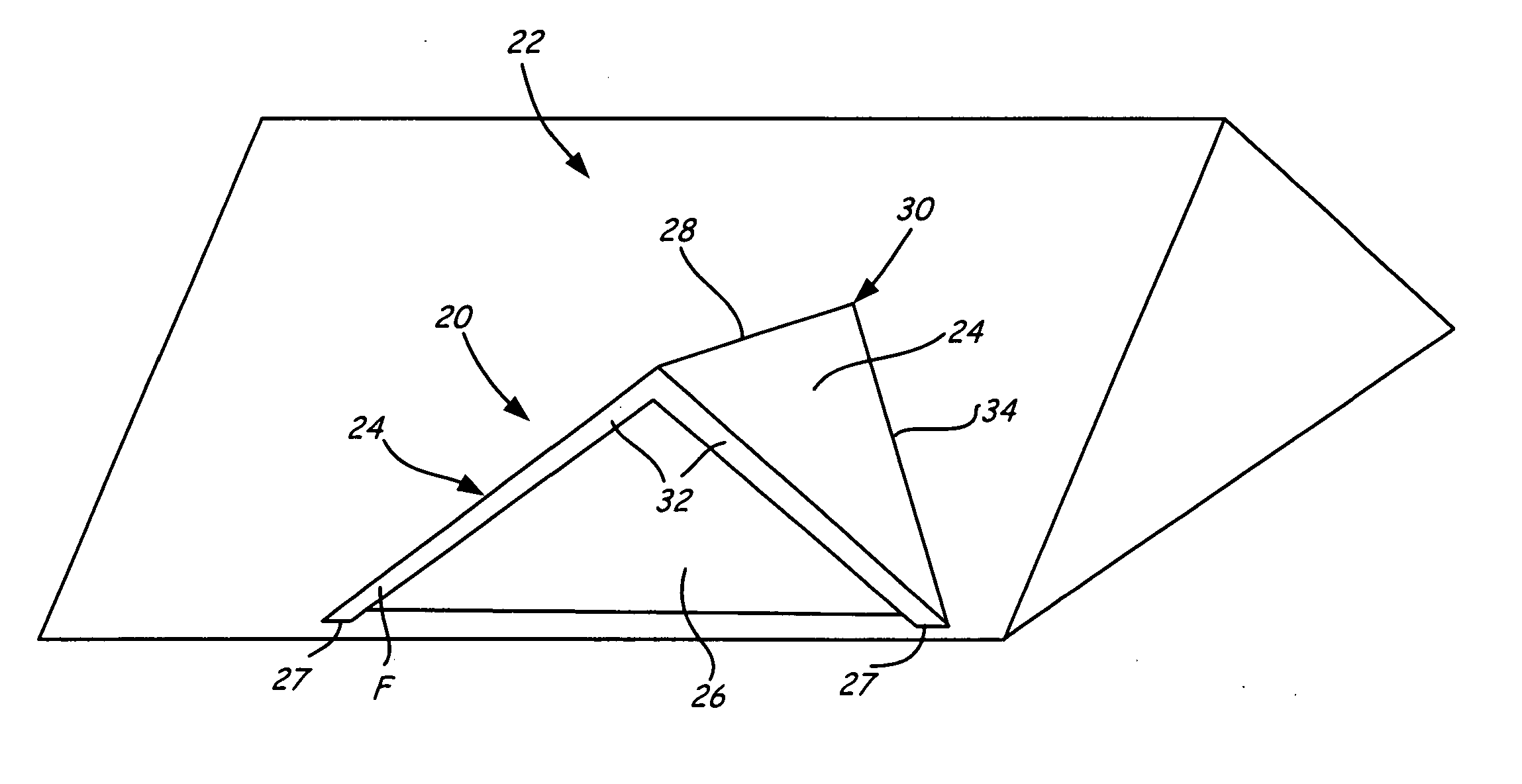
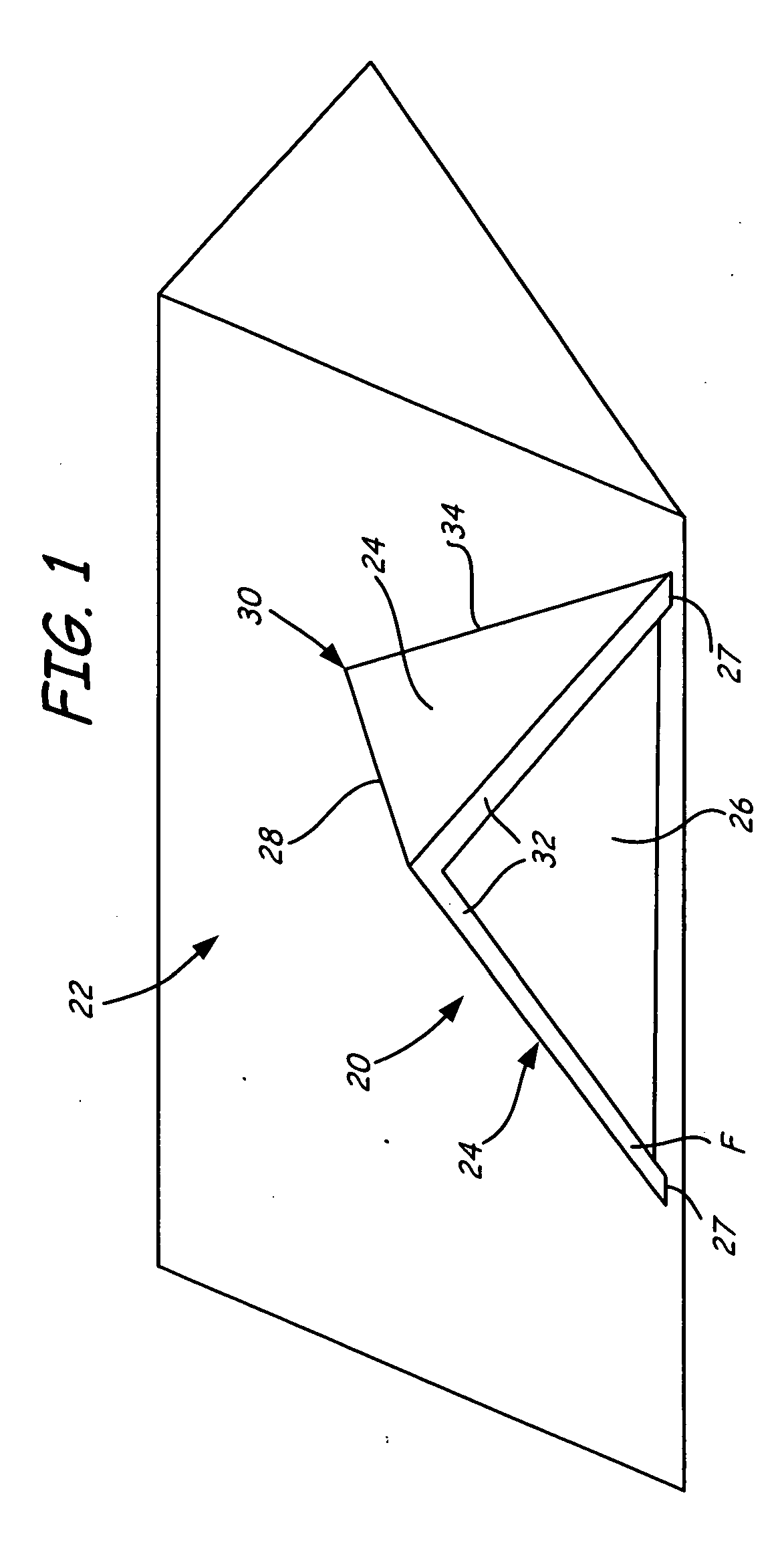
[0022]FIG. 1 is a perspective view of dormer 20 projecting outward from main roof 22. Main roof 22 encloses a primary roofed-in area and dormer 20 encloses a secondary roofed-in area. Dormer 20 includes dormer roof 24, fascia F, gabled end 26, and ridgeline 28 formed in dormer roof 24. Ridgeline 28 originates at dormer point 30, extends along dormer roof 24, and terminates at edge 32 of dormer roof 24 near fascia F. Fascia F has two bottom ends 27, which in dormer 20 of FIG. 1 attach to main roof 22. A pair of valley-lines 34, only one of which is visible in FIG. 1, are located at the intersection of main roof 22 and dormer roof 24. Valley-lines 34 extend outward from dormer point 30 and terminate at edge 32.

[0023] As shown in FIG. 1, both main roof 22 and dormer roof 24 are sloped. Main roof 22 has a main roof slope SMR representing an amount of vertical rise of main roof 22 per an amount of horizontal run of main roof 22. Similarly, dormer roof 24 has a dormer slope SD representi...


PUM


Abstract

The present invention is a method for laying out a dormer that projects outward from a main roof and has a gable end and a dormer roof originating at a dormer point and terminating at an outer edge of the dormer roof near the gabled end. The dormer includes roof sheathing supported by dormer trusses. The dormer trusses include a gable truss and a plurality of valley trusses. The method of the present invention includes receiving a plurality of dormer inputs from a user. A plurality of layouts for the roof sheathing on the dormer roof are generated as a function of the dormer inputs. One or more layouts are then recommended to a user to reduce a quantity of roof sheathing waste.

Description

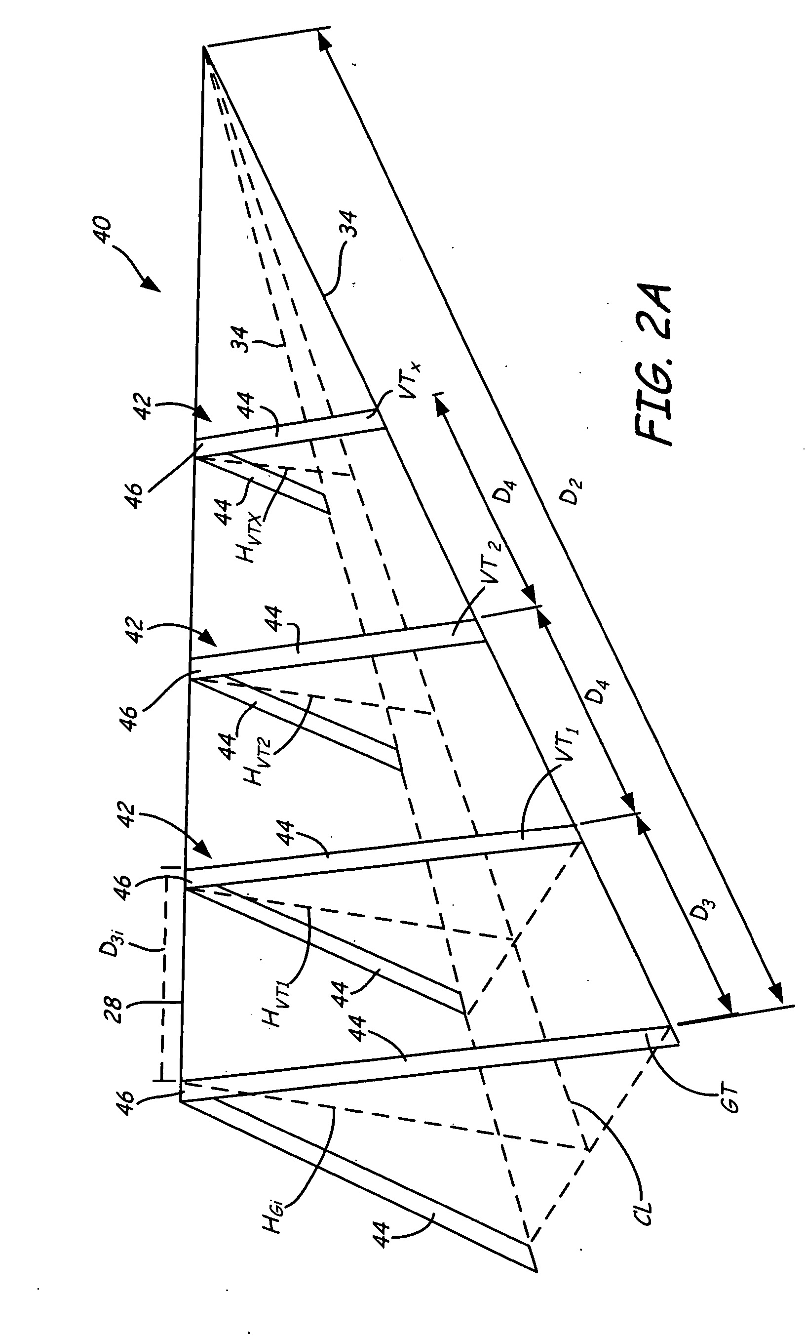
CROSS-REFERENCE TO RELATED APPLICATION(S) [0001] This application claims the benefit of Provisional Application No. 60 / 592,597 filed on Jul. 7, 2004 by Dean Onchuck and entitled “Dormer Calculator.”INCORPORATION BY REFERENCE [0002] The aforementioned Provisional Application No. 60 / 592,597 is hereby incorporated by reference in its entirety.BACKGROUND OF THE INVENTION [0003] The present invention relates generally to the field of dormer construction. In particular, the present invention relates to a method for laying out the materials for constructing a dormer. [0004] A dormer is a roofed structure projecting outward from the sloping plane of a main roof. A dormer may be included in a roof to increase headroom, improve ventilation, provide a vertical surface suitable for installing windows or other openings, or to add to the aesthetic appeal of a building. [0005] The framework of a dormer typically consists of a series of spaced trusses which support roof sheathing. These dormer trus...

Claims


Application Information

Patent Timeline
IPC IPC(8): E04G23/00
CPCE04B7/18
Inventor ONCHUCK, DEAN
Owner ONCHUCK DEAN
Learn More