Automatic moving clerestory window

A technology for moving and pulling skylights, which is applied to roofs, buildings, building structures, etc. It can solve the problems that skylight equipment cannot be opened and closed automatically and the degree of opening and closing, lack of window automation, and manual opening and closing of skylights is inconvenient. Achieve the effect of simple structure, easy assembly and low cost

Inactive Publication Date: 2007-09-26
JIANGNAN UNIV
View PDF0 Cites 0 Cited by
  • Summary
  • Abstract
  • Description
  • Claims
  • Application Information

AI Technical Summary

Problems solved by technology

[0002] At present, the known sunroof equipment cannot automatically open, close and control the degree of opening and closing, and the manual opening and

Method used


Image

  • Automatic moving clerestory window
  • Automatic moving clerestory window
  • Automatic moving clerestory window

Examples


Embodiment Construction

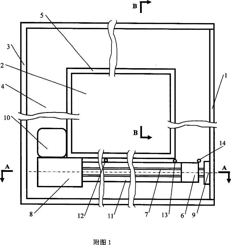
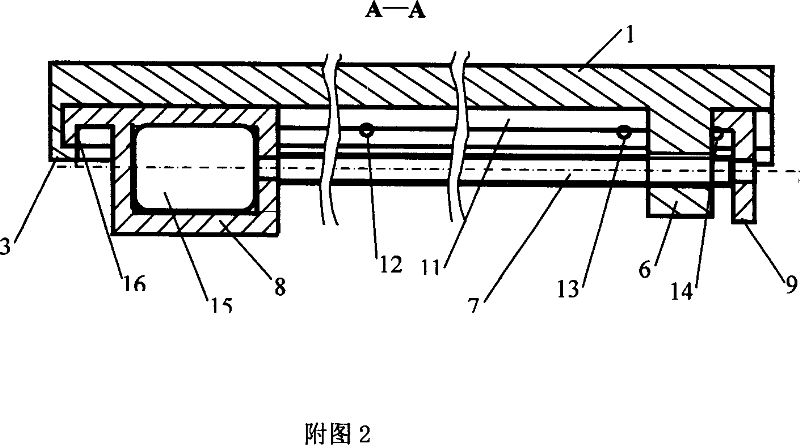
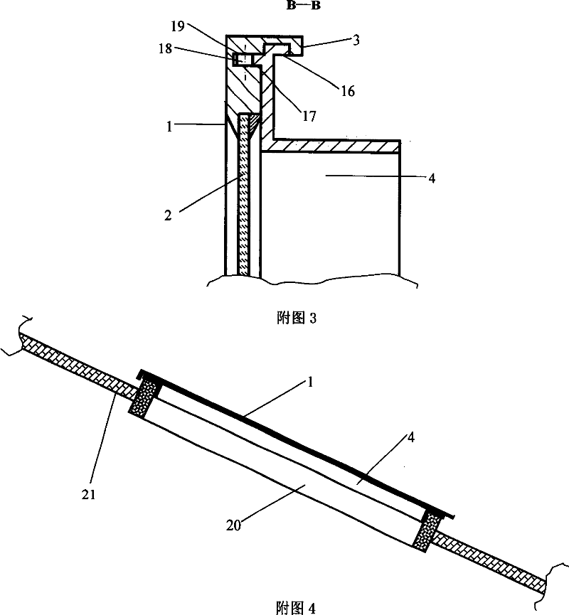
[0014] In the embodiment shown in the drawings, the sliding window sash composed of the outer frame (1) tightly embedded with glass (2) is assembled on the fixed window frame (4) with slide rails (17). Controlled and driven by the control system, the motor (15)-screw (7)-screw nut (6) mechanism drives the sliding. Move and pull the left and right sides of the sash frame (1) to make a groove (19) along the edge, and the groove is embedded with a pulley (18) that leans on the fixed window frame slide rail (17) to roll; the left side of the frame (1) , the outer edge of the right side and the uplink side are downward, and then vertically folded inward twice to form a rainproof and pry-proof edge (3). The left and right sides of the fixed window frame (4) are made on the top slide rail (17) along the edge convex shoulder that is rollingly matched with the pulley (18) in the sash frame (1) groove (19); the fixed window frame ( 4) The left, right and upside outer edges are vertical...


PUM


Abstract

An automatic drawing dormer arranges a drawing leaf with groove at the frame on the fixed window frame with shoulder sliding track, a motor-lead screw-screw structure, a power source, and a drawing control system to form an incline dormer with automatic control, simple installment, simple operation, rain-proof, and theft-proof functions or the like.

Description

Technical field [0001] The invention relates to a roof skylight device. Background technique [0002] At present, the known sunroof devices cannot automatically open and close and control the degree of opening and closing, and the manual opening and closing operation of the sunroof is very inconvenient. Especially in many "automated buildings", the lack of automation of windows has become a shortcoming. Thereby urgently need to develop a kind of convenient, practical automatic skylight equipment, to replace the common skylight commonly used in buildings at present, and then fully realize building automation. Contents of the invention [0003] In order to realize the automatic control of the opening and closing of the skylight and the degree of opening and closing, the invention provides an automatic sliding skylight. It is assembled on a fixed window frame with slide rails with a sliding window sash with grooves on the frame. The window sash is driven by a screw and a nu...

Claims


Application Information

Patent Timeline
IPC IPC(8): E04D13/035
Inventor 屈百达
Owner JIANGNAN UNIV
Why Eureka
Try Eureka