
Rotating specimen holder

a specimen and rotating technology, applied in the field of specimen holders, can solve the problems of inability to perform appropriate observations, high labor and time, and inability to rotate specimens efficiently, and achieve the effect of efficient rotation of specimens, no obstruction of observation, and no labor and tim

Inactive Publication Date: 2006-02-23
JEOL LTD
View PDF1 Cites 9 Cited by
  • Summary
  • Abstract
  • Description
  • Claims
  • Application Information

AI Technical Summary

Benefits of technology

[0023] It is an object of the present invention to provide a specimen holder permitting a specimen to be rotated efficiently such that the specimen can be observed without hindrance. It is another object of the present invention to provide an observation system fitted with this specimen holder. It is a further object of the present invention to provide a method of rotating a specimen efficiently during observation of the specimen such that the observation is not hindered.

Problems solved by technology

Much labor and time have been required.
Hence, the efficiency is not high.
This makes it impossible to perform appropriate observations.
If the ice that covers the specimen 3 is crystallized, the transparency of the ice deteriorates, making it impossible to perform appropriate observations.

Method used


Image

  • Rotating specimen holder
  • Rotating specimen holder
  • Rotating specimen holder

Examples


Embodiment Construction

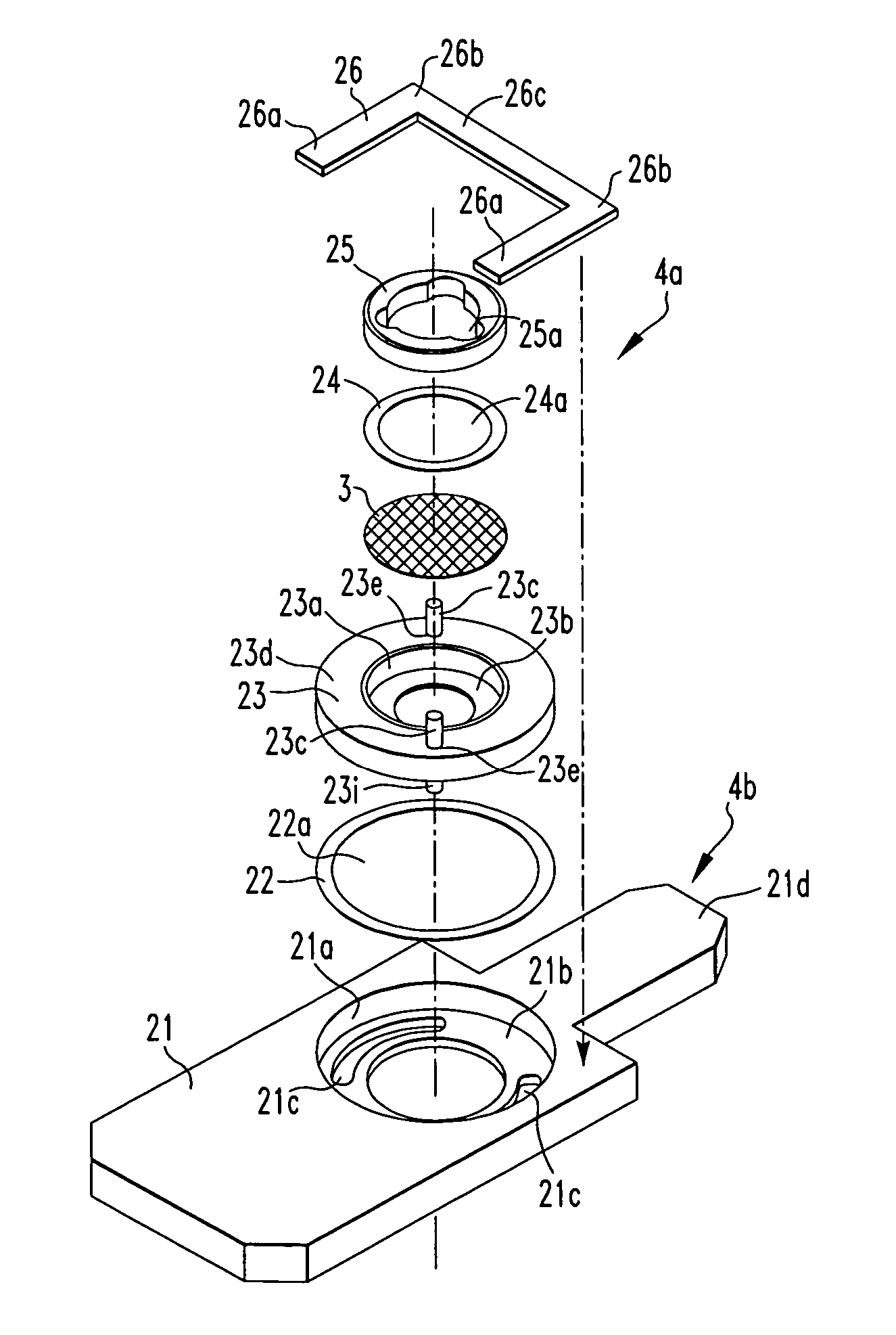
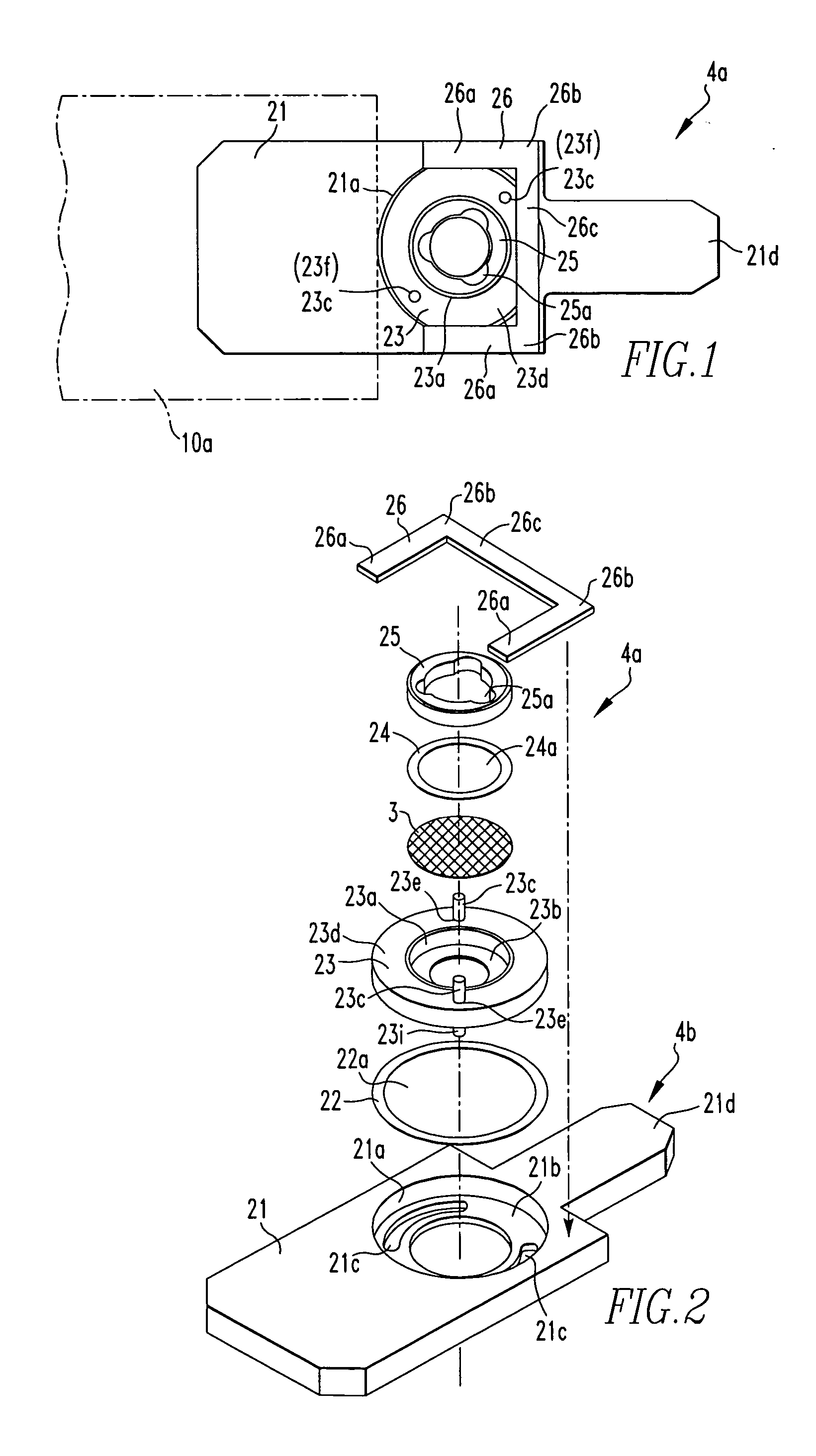
[0039] The preferred embodiments of the present invention are hereinafter described with reference to the accompanying drawings. FIG. 1 is a plan view of a specimen holder according to an embodiment of the present invention. FIG. 2 is an exploded view of this specimen holder, showing its structure.

[0040] Referring to FIG. 1, the specimen holder, indicated by reference numeral 4a, has a holder body 21, a specimen-holding member 23 for holding a specimen, a screw 25 for fixing the specimen to the specimen-holding member 23, and a leaf spring 26 for anchoring the specimen-holding member 23 to the holder body 21.

[0041] As also shown in FIG. 2, the holder body 21 of the specimen holder 4a is provided with a circular hole 21a for accommodating the specimen-holding member 23. A step surface 21b acting as a support surface is formed inside the circular hole 21a. Two opposite slots 21c are formed in the step surface 21b. The holder body 21 has a fitting portion 21d that is narrower than th...


PUM

PropertyMeasurementUnit
fluorescentaaaaaaaaaa
angleaaaaaaaaaa

Abstract

A specimen holder having a holder body and a specimen-holding member is used. The holder body has a hole in which a step surface is formed. The specimen-holding member is supported from the step surface in the hole of the holder body and positioned within the hole. Arc-shaped slots are formed in the step surface. The specimen-holding member has an opening that accommodates the specimen. The specimen-holding member also has a surrounding portion through which rod-like members extend. The rod-like members have lower-end portions inserted in the slots formed in the step surface. The rod-like members also have upper-end portions. The specimen-holding member holding the specimen is rotated by rotating the upper-end portions of the rod-like members.

Description

BACKGROUND OF THE INVENTION [0001] 1. Field of the Invention [0002] The present invention relates to a specimen holder used in an observation system, such as a transmission electron microscope. [0003] 2. Description of Related Art [0004] A transmission electron microscope has a microscope column in which electron optics are positioned. In some instruments, a goniometer (goniostage) supporting a specimen holder used to hold a specimen is mounted in the microscope column. A specimen exchange chamber is mounted in a position opposite to the goniometer. In this case, this specimen exchange chamber is fitted with a transport device for transporting the specimen holder into the microscope column. [0005] The structure of such a transmission electron microscope is schematically shown in FIG. 10, where the microscope or an observation system is generally indicated by reference numeral 1. This microscope 1 has an electron gun 14 for emitting and accelerating an electron beam 12, which is cont...

Claims


Application Information

Patent Timeline
Patent Type & Authority Applications(United States)
IPC IPC(8): G21K5/10G01N23/04G01N1/28G01Q10/00G21K7/00H01J37/20H01J37/26
CPCH01J37/20H01J2237/204H01J2237/20214H01J37/26
Inventor MORIYA, KOJI
Owner JEOL LTD
Learn More