Method of controlling a vehicle wheel suspension

a technology of vehicle wheels and suspensions, applied in the direction of resilient suspensions, interconnection systems, vehicle components, etc., can solve the problems of impaired vehicle traction ability, and achieve the effect of improving the traction of the vehicl

Inactive Publication Date: 2006-02-23
DAIMLER AG
View PDF2 Cites 9 Cited by
  • Summary
  • Abstract
  • Description
  • Claims
  • Application Information

AI Technical Summary

Benefits of technology

[0006] In a method for controlling the wheel suspension of a motor vehicle having an anti-roll bar connected to a front axle, an anti-roll bar connected to a rear axle, at least one sensor, one control unit and a circuit including an operating medium with a supply reservoir, a directional control device and an actuator for each anti-roll bar in which each actuator is assigned a particular section of the circuit, different sections of the circuit are in control of different actuators so as to be actuated in opposite directions to one another as a function of vehicle operating conditions in order to improve the traction of the vehicle on an uneven underlying surface.
[0007] In this way, it can be ensured that all the wheels of the vehicle are always subjected to approximately the same loading. As a result, differences of wheel loads of the vehicle wheels are reduced and the traction of the vehicle is increased.
[0008] The actuators are preferably continuously actuated. The position of the actuators is thus continuously adapted to changes in the underlying surface. As a result, the movements of the body of the vehicle on an uneven underlying surface are reduced. This results in softer vehicle movements and a greater degree of driving comfort. The method is particularly suitable for slow travel on uneven terrain.

Problems solved by technology

However, the traction capability of the vehicle may be impaired on an uneven underlying surface.

Method used


Image

  • Method of controlling a vehicle wheel suspension
  • Method of controlling a vehicle wheel suspension
  • Method of controlling a vehicle wheel suspension

Examples


Embodiment Construction

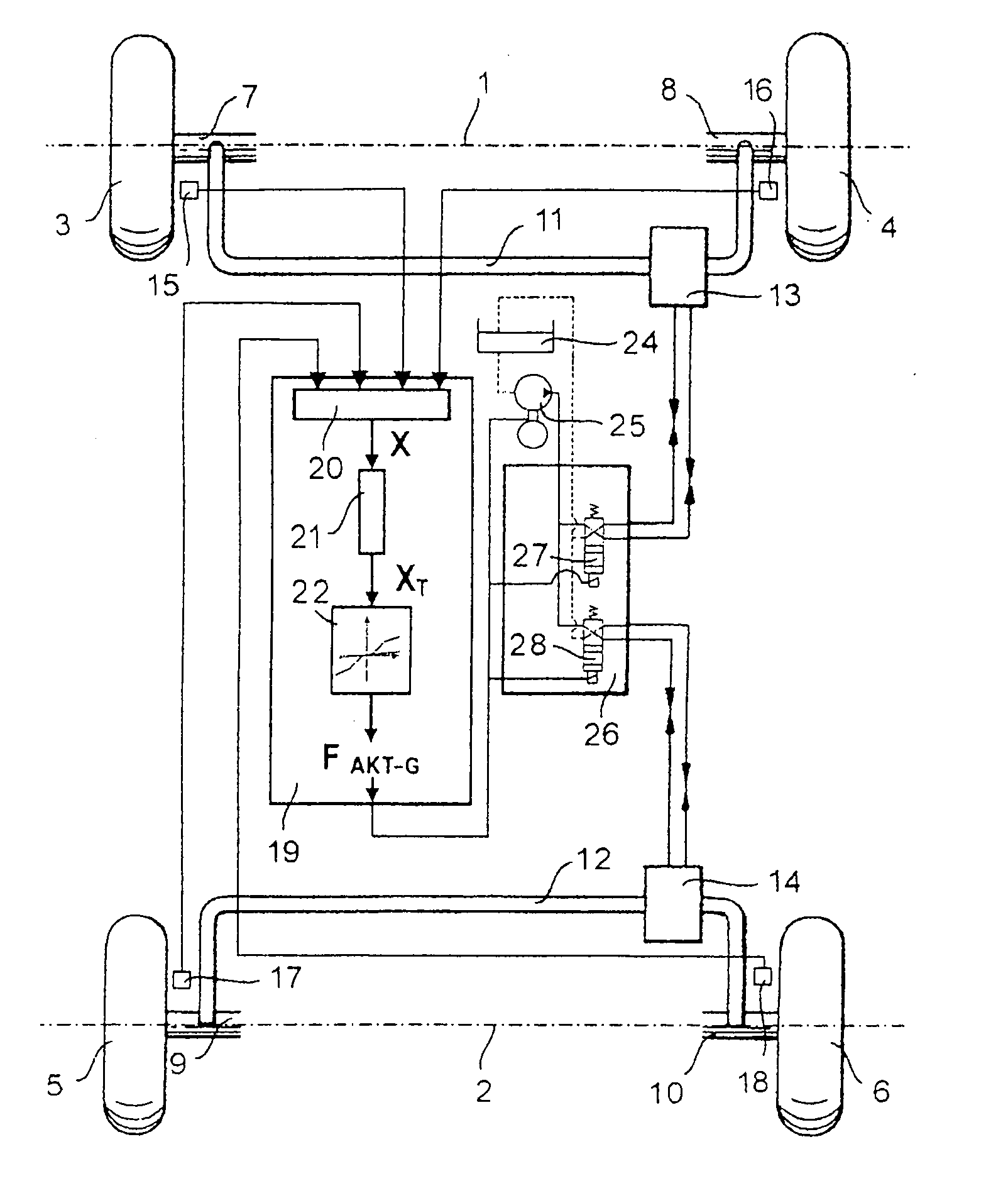
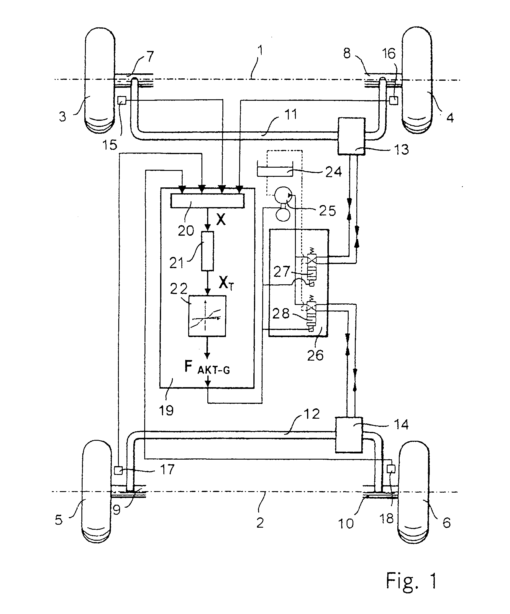
[0020]FIG. 1 is a schematic view of a preferred active chassis of a motor vehicle. Two vehicle wheels 3 and 4 are arranged on a front axle 1 and two vehicle wheels 5 and 6 are arranged on a rear axle 2. Each vehicle wheel 3, 4, 5 and 6 is rotatably mounted on a wheel carrier 7, 8, 9 and 10. Here, the vehicle wheel 3 is assigned the wheel carrier 7, the vehicle wheel 4 is assigned the wheel carrier 8, the vehicle wheel 5 is assigned the wheel carrier 9 and the vehicle wheel 6 is assigned the wheel carrier 10. The wheel carriers 7, 8, 9, 10 are moveably attached to a body of a vehicle (not illustrated). The distance between a vehicle wheel 3, 4, 5 or 6 and the body of the vehicle which can be varied by means of a moveable wheel carrier 7, 8, 9 or 10 is referred to as a spring travel value nLV, nRV, nLH and nRH. Here, the indices: V=front axle, H=rear axle, L=left-hand, R=right-hand. The wheel carriers 7 and 8 of the front axle 1 are connected to one another by means of a common anti-r...


PUM


Abstract

In a method for controlling the wheel suspension of a motor vehicle having an anti-roll bar for a front axle, an anti-roll bar connected to a rear axle, at least one sensor, one control unit and a circuit including an operating medium with a supply reservoir, a directional control device and an actuator for each anti-roll bar with each actuator being assigned a particular section of the circuit, different sections of the circuit are in control of different actuators so as to be actuated in opposite directions to one another as a function of vehicle operating conditions, in order to improve the traction of the vehicle on uneven underlying surfaces.

Description

[0001] This is a Continuation-In-Part Application of International Application PCT / EP2004 / 003099 filed 24 Mar. 2004 and claiming the priority of German application 103 14 251.7 filed 29 Mar. 2003.BACKGROUND OF THE INVENTION [0002] The invention relates to a method of controlling a vehicle wheel suspension including front and rear axle anti-roll bars and a device for carrying out the method. [0003] It is known to use anti-roll bars to improve the driving behavior in motor vehicles. When the vehicle leans for example during cornering the anti-roll bars are subjected to torsion in order to counteract rolling movements of the vehicle. Such a system is known from laid-open patent application DE 43 37 765 A1. [0004] Patent DE 42 37 708 C1 discloses a device for influencing rolling movements of a vehicle. The device has anti-roll bars which can be controlled as a function of the spring compression of the wheel by means of actuators. Each actuator is assigned a non return valve arrangement ...

Claims


Application Information

Patent Timeline
Patent Type & Authority Applications(United States)
IPC IPC(8): B60G21/045B60G21/055B60G17/015B60G17/056B60G21/10
CPCB60G17/056B60G2500/02B60G21/0555
Inventor DOERR, ERNST-LUDWIGRUEDT, WOLFGANGSHINODA, KENJISPINDLER, HANS-GERHARD
Owner DAIMLER AG
Why Eureka
Try Eureka