Foldable shooting chair

a folding chair and folding technology, applied in the field of folding chairs, can solve the problems of not being able to easily change the height, not being able to easily transport the known shooting chairs from one area of use to another, etc., and achieve the effect of reducing labor intensity, reducing labor intensity and reducing labor intensity

Inactive Publication Date: 2006-02-23
HOWELL LARRY D +1
View PDF12 Cites 6 Cited by
  • Summary
  • Abstract
  • Description
  • Claims
  • Application Information

AI Technical Summary

Benefits of technology

[0010] Principal objects of the present invention are to provide a shooting chair that will be stable, easily transported, even carried by hand, and that can be set-up for use at a target range or in the field in a minimum amount of time and with a minimum amount of effort.
[0011] Another object of the invention is to provide a shooting chair that when folded to be carried, has handle means that will provide for balanced carrying, even as a person carrying the shooting chair travels over irregular terrain.
[0016] The support arm is mounted on a back support post on which the seat back is mounted and extends outwardly and forwardly of the padded seat. A cushioned arm rest is mounted to be positioned along one side or an opposite side of a forwardly extending portion of the support arm. The choice of positioning of the cushioned arm rest is determined by whether the shooting chair is set up for a right handed shooter or a left handed shooter. The support arm is removed from a set-up shooting chair and is repositioned to become a carrying handle that will balance the load weight of the folded shooting chair, as it is carried.
[0019] The support foot projects from the central tube at the side of the central tube opposite to the connection of the one leg to the central tube to rest upon the ground when the shooting chair is in its folded condition. When resting on the support foot, the repositioned support arm has a bend therein that extends upwardly to serve as a carrying handle, to be easily grasped by a user.

Problems solved by technology

Known shooting chairs have not been easily transported from one area of use to another area of use.
This is due not only to the weight and bulkiness of the shooting chairs, but also because they often do not include any means for easily changing the height and direction of the support arm for the muzzle end of the gun when it is used in the field, to shoot at an animal.

Method used


Image

  • Foldable shooting chair
  • Foldable shooting chair
  • Foldable shooting chair

Examples


Embodiment Construction

[0033] Referring now to the Drawings:

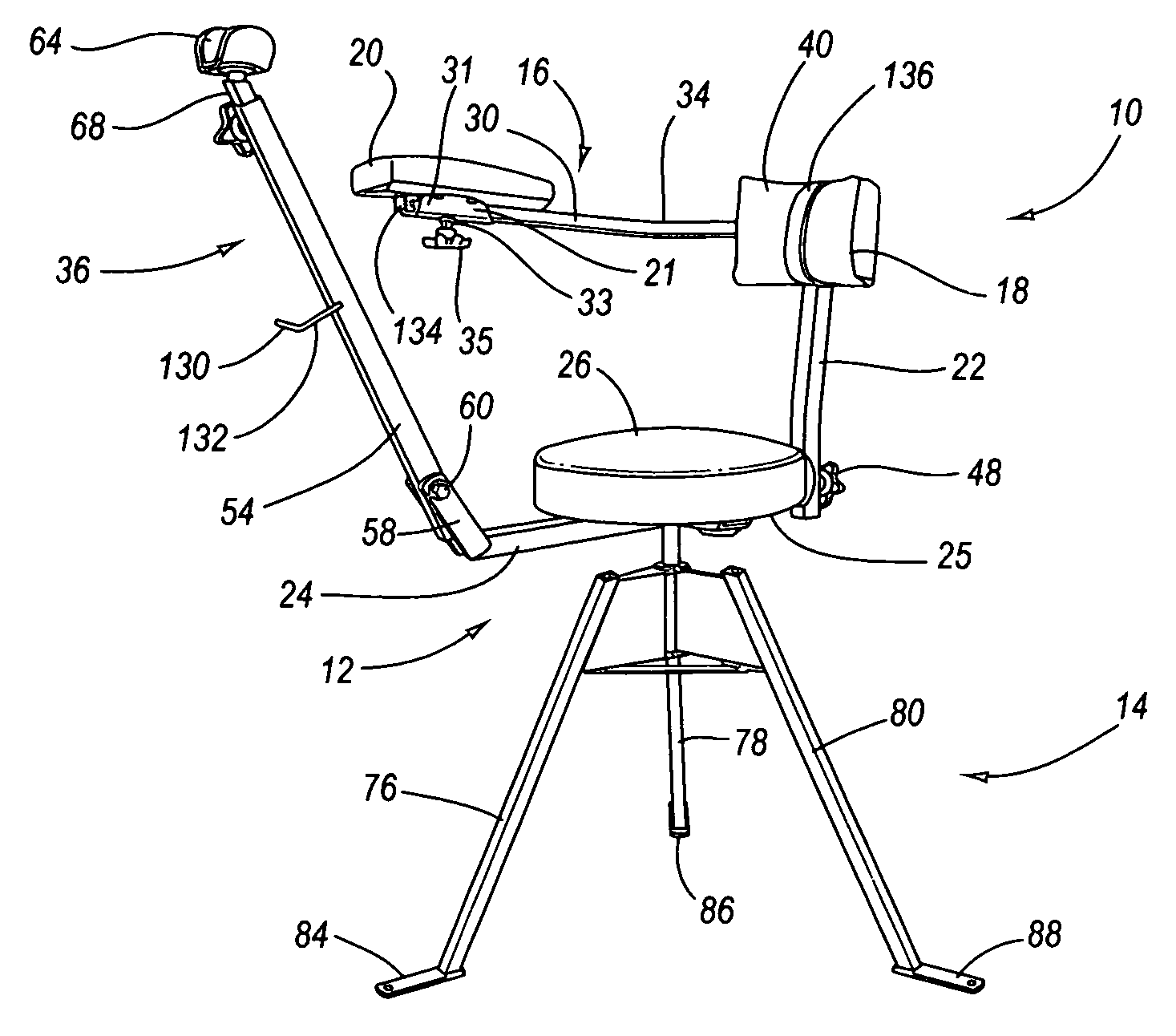
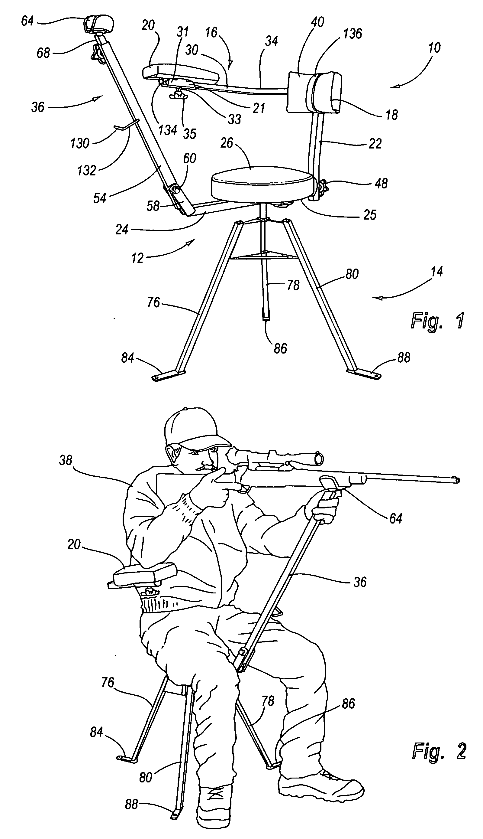
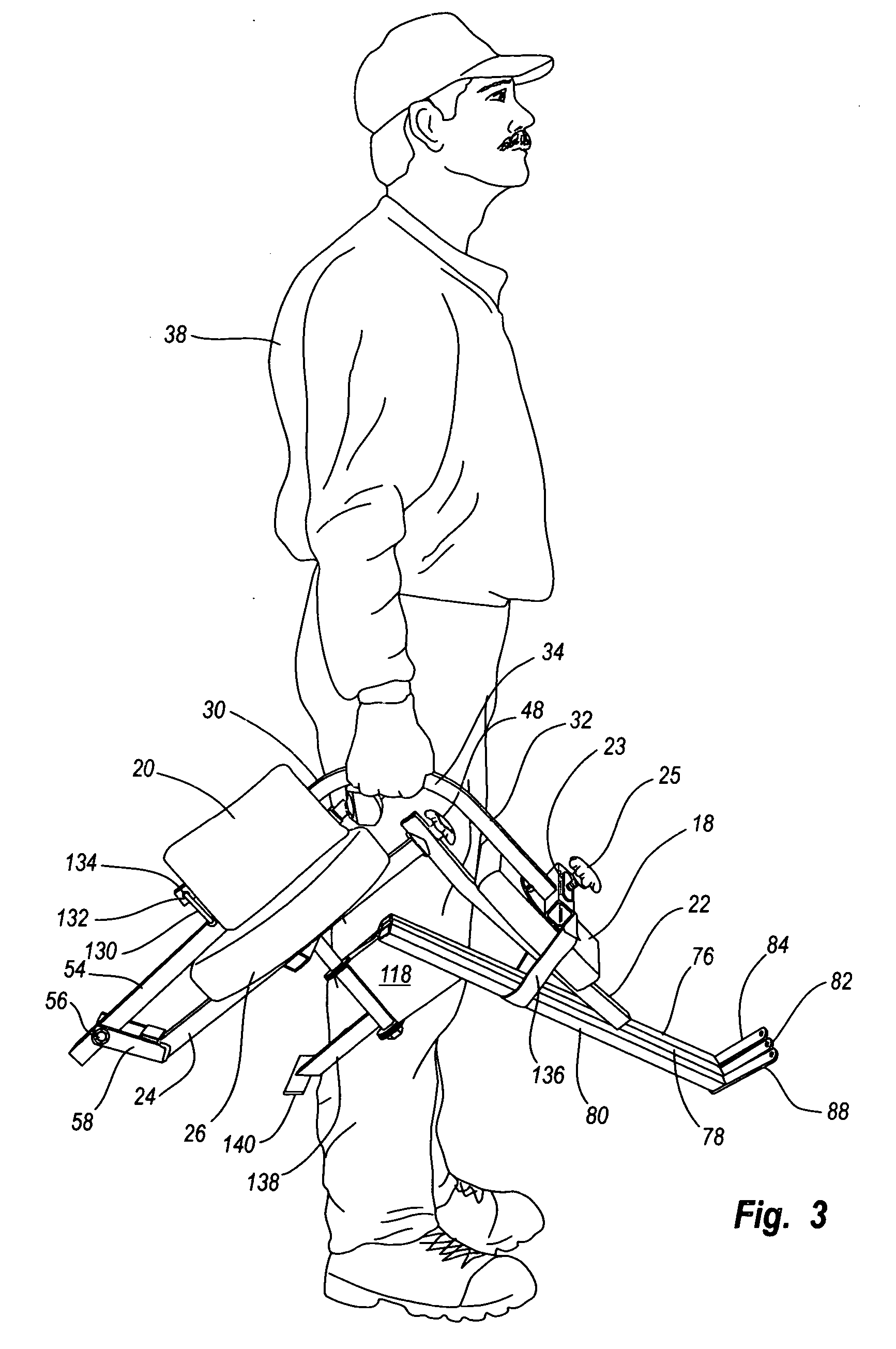
[0034] In the illustrated preferred embodiment of the invention, the shooting chair, shown generally at 10 includes a stool, shown generally at 12 and a tripod leg assembly 14.

[0035] A support arm 16 includes a back rest 18 and an arm rest 20. The support arm 16 is removably mounted on an upright extending support post 22.

[0036] Support post 22 projects upwardly from one end of a seat brace 24 connected to the undersurface 25 of seat 26 (preferably padded) of the stool 12.

[0037] Support arm 16 extends from the support post 22 on one side of the padded seat 26 and then is curved a full ninety degrees to extend alongside the seat. Support arm 16 has the back rest 18 secured thereto at an end of one straight extension 30 of the support arm 16. The support arm has straight extensions 30 and 32 extending from opposite ends of a right angle curved bend 34. The support arm 16 curves to extend alongside a user person 38 sitting on the padded seat cus...


PUM


Abstract

A foldable shooting chair that will provide a sturdy support for a long gun shooter and includes a tripod base with legs that will fold together. A stool, including a padded seat rotatably mounted on the base and a seat back, support arm and shooting arm carried by and rotatable with the padded seat, the support arm being removable for positioning as a support for either a right or left-handed shooter and as a handle when the tripod legs are folded together.

Description

CROSS-REFERENCE TO RELATED APPLICATIONS [0001] Not applicable. STATEMENT REGARDING FEDERALLY SPONSORED RESEARCH OR DEVELOPMENT [0002] Not applicable. REFERENCE TO A MICROFICHE APPENDIX [0003] Not applicable. BACKGROUND OF THE INVENTION [0004] 1. Field of the Invention [0005] This invention relates to shooting chairs used by persons firing guns, and particularly, shooting long guns. [0006] 2. Prior Art [0007] Shooting chairs have been used for years. Generally, the chairs have supporting legs, a seat, and a support arm that will support the muzzle end of a gun being fired. The known shooting chairs are generally made of heavy metal or wood materials, so that they will remain very stable during firing. For the most part, such shooting chairs have been used on shooting ranges and at target practice areas to allow a shooter to “sight-in” his gun. While any gun can be fired while sitting on the shooting chair, the chair is most often used during the firing of rifles or other long guns. [...

Claims


Application Information

Patent Timeline
Patent Type & Authority Applications(United States)
IPC IPC(8): A47C7/54
CPCA01M31/02
Inventor HOWELL, LARRY D.SCHRECENGOST, SHAWN
Owner HOWELL LARRY D
Why Eureka
Try Eureka