Reading-line adjusting device of image scanner

a technology of image scanner and adjusting device, which is applied in the direction of discharge tube/lamp details, instruments, photoelectric discharge tubes, etc., can solve the problems of impaired scanning quality, and achieve the effect of minimizing the adverse influen

Inactive Publication Date: 2006-02-23
TECO IMAGE SYST
View PDF3 Cites 3 Cited by
  • Summary
  • Abstract
  • Description
  • Claims
  • Application Information

AI Technical Summary

Benefits of technology

[0007] It is an object of the present invention to provide a reading-line adjusting device capable of adjusting the reading line direction of an image sensing module to be substantially perpendicular to the scanning direction, thereby minimizing the adverse influence resulting from the reading line direction's deviation.

Problems solved by technology

Therefore, the scanning quality is impaired.

Method used


Image

  • Reading-line adjusting device of image scanner
  • Reading-line adjusting device of image scanner
  • Reading-line adjusting device of image scanner

Examples


Embodiment Construction

[0024] The present invention will now be described more specifically with reference to the following embodiments. It is to be noted that the following descriptions of preferred embodiments of this invention are presented herein for purpose of illustration and description only. It is not intended to be exhaustive or to be limited to the precise form disclosed.

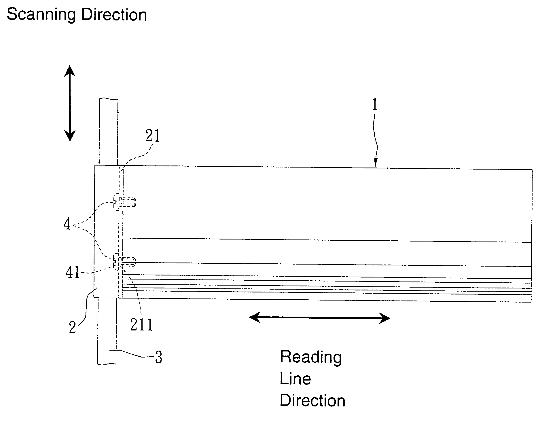
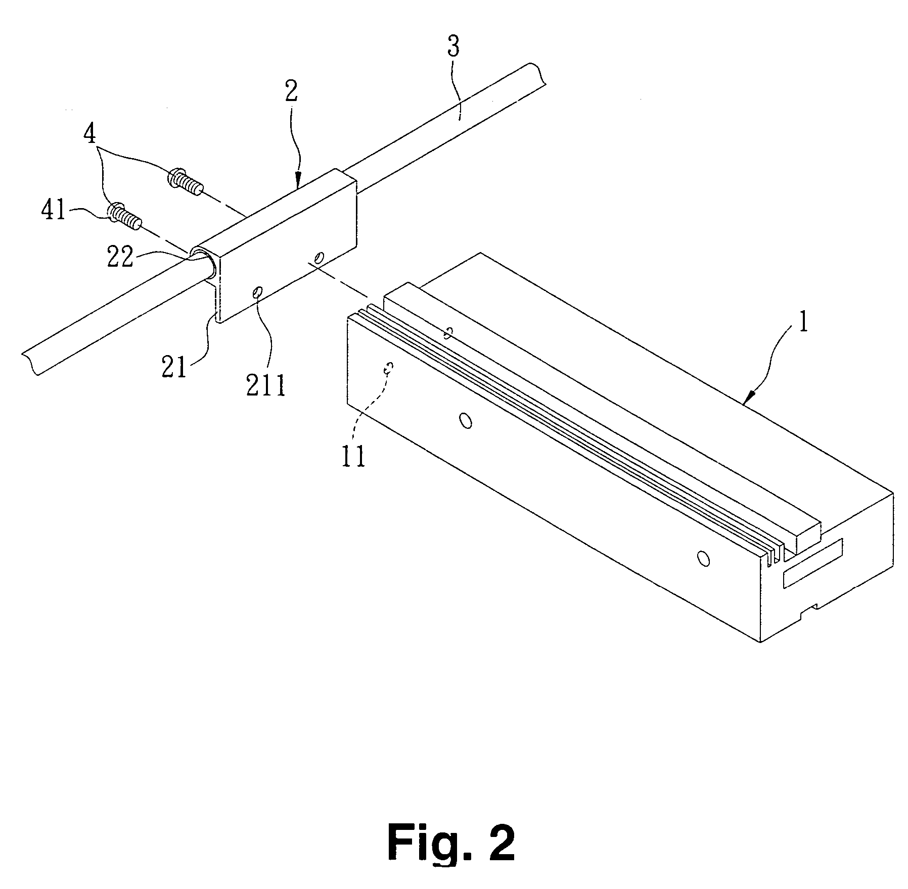
[0025] Referring to FIGS. 2, 3 and 4, a reading-line adjusting device according to a preferred embodiment of the present invention is shown. The reading-line adjusting device principally comprises an image sensing module 1, a bush member 2, a shaft 3 and a fixing and adjusting member 4.

[0026] The image sensing module 1 has therein several optical elements including a light source, a reflective mirror, a lens set, and a photoelectric conversion device such as a charge couple device (CCD). The functions of the reflective mirror, the lens set and the CCD element are similar to those described above and are not intended to be desc...


PUM


Abstract

A reading-line adjusting device of an image scanner includes an image sensing module, a shaft, a bush member, and a fixing and adjusting member. The image sensing module has a reading line for sensing an electronic signal of an image. The shaft is arranged in a first direction. The bush member includes a base and a bushing body. The base is coupled with the image sensing module. The bushing body is sleeved around the shaft and moved along the shaft. The fixing and adjusting member is used for fixing the base of the bush member onto the image sensing module and adjusting an angle between the base and the image sensing module such that the reading line of the image sensing module is arranged in a second direction.

Description

FIELD OF THE INVENTION [0001] The present invention relates to a reading-line adjusting device of an image scanner, and more particularly to a reading-line adjusting device capable of adjusting the reading line direction of an image sensing module of the image scanner. BACKGROUND OF THE INVENTION [0002] With increasing development, electronic products are more powerful and the sizes thereof are developed toward minimization. In addition to these requirements, the electronic product should have desired quality. For example, scanners are widely used for scanning, opaque objects and processing the image information into analog, or digital forms. Examples of the opaque objects include paper sheets, photographs, etc. In order to achieve better image quality, the components of the scanner should be properly selected and assembled. As known, the type of the light source and the brightness of the reflective light are major factors influencing the image quality of the scanner. [0003] A typic...

Claims


Application Information

Patent Timeline
Patent Type & Authority Applications(United States)
IPC IPC(8): H04N1/04
CPCH04N1/028H04N1/1013H04N2201/0442H04N2201/02402H04N2201/0432H04N1/103
Inventor YEH, MING TEOU, YUN HSIU
Owner TECO IMAGE SYST
Why Eureka
Try Eureka