

Resonance transducer
a resonance transducer and transducer technology, applied in the field of resonance transducers, can solve the problems of inefficiency of controlling the circuit described in [2] and the proportional output voltage of the secondary circuit, and achieve the effect of efficient triggering of the resonance transducer
Inactive Publication Date: 2006-02-23
PULS GMBH
View PDF8 Cites 7 Cited by
- Summary
- Abstract
- Description
- Claims
- Application Information
AI Technical Summary
Benefits of technology
[0003] The object of the invention is to provide a resonance transducer which allows a controlling of the output voltage, while such controlling of the output voltage is efficient and possible without the elaborative use of expensive components. It is further an object of the invention to provide for a possibility of an efficient triggering of the resonance transducer and, finally, a switched mode power supply including a resonance transducer according to the invention.
Problems solved by technology
The resonance transducers known from prior art have the disadvantage that the output voltage of the secondary circuit is proportional to the input voltage of the resonance transducer and is predefined to a large extent by the turns ratio of the two coils in the resonance transducer.
Further, controlling the circuits described e.g. in [2] is inefficient, because the resonance current flows through all the switching elements which accordingly have to be designed in order to perform in a powerful manner.
Method used
View moreImage
Smart ImageViewing Examples

Examples
Embodiment Construction
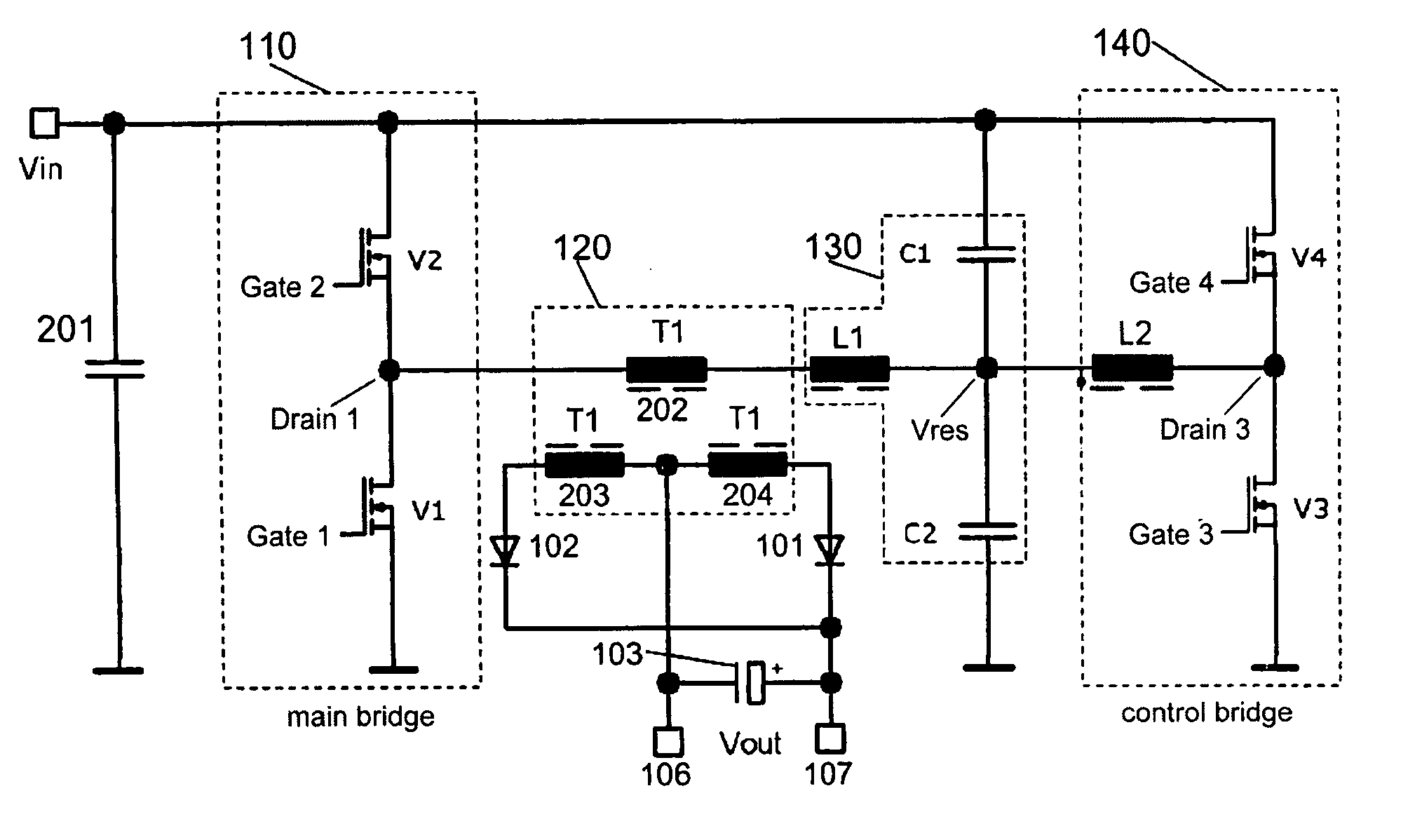
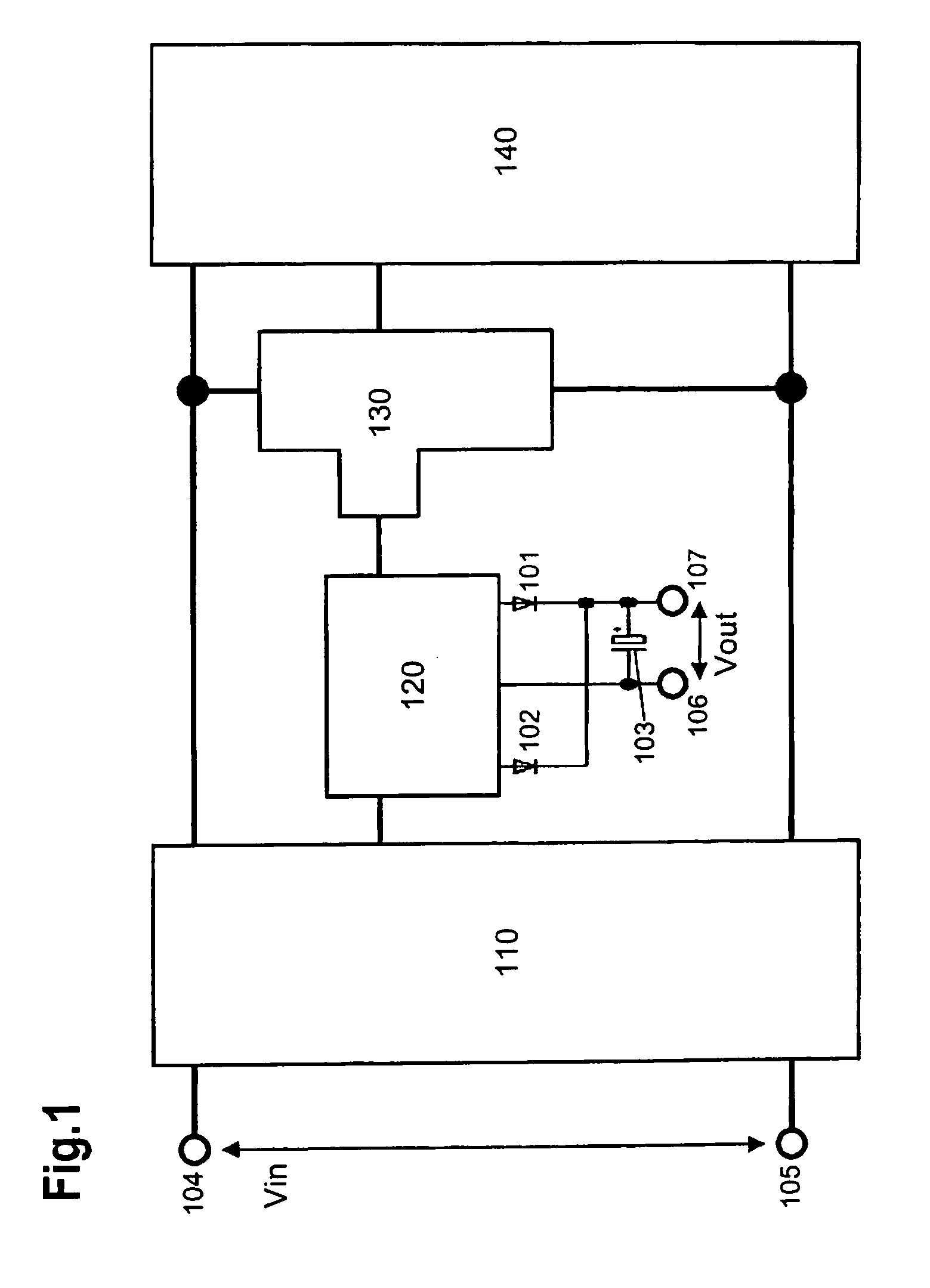
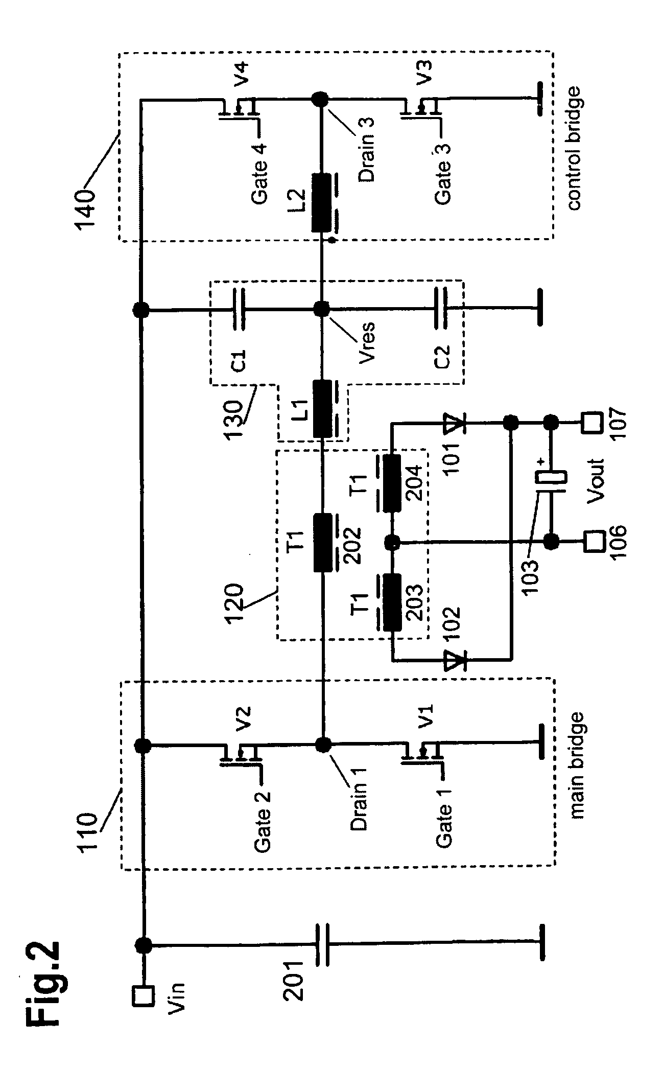
[0005] In FIG. 1 there is shown a block diagram of a resonance transducer. Here, an input signal Vin is linked with a main bridge 110 through inputs 104 and 105. The inputs 104 and 105 can be configured as input terminals, connectors or pins, for example. Input 105 preferably may be at ground potential, so that in particular input 104 receives the input signal + / − Vin (with regard to ground potential).
Login to View More PUM
 Abstract
There is provided a resonance transducer including a main bridge linked with an input signal. The resonance transducer includes a transformer assembly across which an output signal can be tapped, a resonance circuit and a control circuit. In this arrangement, the transformer assembly is linked with the main bridge and the resonance circuit, the resonance circuit is further linked with the main bridge and the control circuit, and the control circuit is further linked with the main bridge.
Description
FIELD OF THE INVENTION [0001] The invention relates to a resonance transducer, in particular a triggering of the resonance transducer as well as to a power supply including a resonance transducer according to the invention. BACKGROUND OF THE INVENTION [0002] The resonance transducers known from prior art have the disadvantage that the output voltage of the secondary circuit is proportional to the input voltage of the resonance transducer and is predefined to a large extent by the turns ratio of the two coils in the resonance transducer. Further, controlling the circuits described e.g. in [2] is inefficient, because the resonance current flows through all the switching elements which accordingly have to be designed in order to perform in a powerful manner. SUMMARY OF THE INVENTION [0003] The object of the invention is to provide a resonance transducer which allows a controlling of the output voltage, while such controlling of the output voltage is efficient and possible without the e...
Claims
Login to View More Application Information
Patent Timeline
 Patent Type & AuthorityApplications(United States)
IPC IPC(8): H02M3/335
CPCH02M3/337Y02B70/1491H02M2001/0058Y02B70/10H02M1/0058H02M3/33571H02M3/01
InventorFRIEDRICH, HEINERPFEIFER, BERND
OwnerPULS GMBH