Electrical connector having protecting protrusions

Inactive Publication Date: 2006-02-23
HON HAI PRECISION IND CO LTD
View PDF7 Cites 27 Cited by
  • Summary
  • Abstract
  • Description
  • Claims
  • Application Information

AI Technical Summary

Benefits of technology

[0006] Accordingly, a main object of the present invention is to provide a new LGA connector

Problems solved by technology

However, the connector has a shortcoming that there is no protecting means for the terminals.
When the connector is collided by an exterior object, the spring arm is prone to be accidental damaged because of undue forc

Method used


Image

  • Electrical connector having protecting protrusions
  • Electrical connector having protecting protrusions
  • Electrical connector having protecting protrusions

Examples


Example

[0016] Reference will now be made to the drawings to describe the present invention in detail.

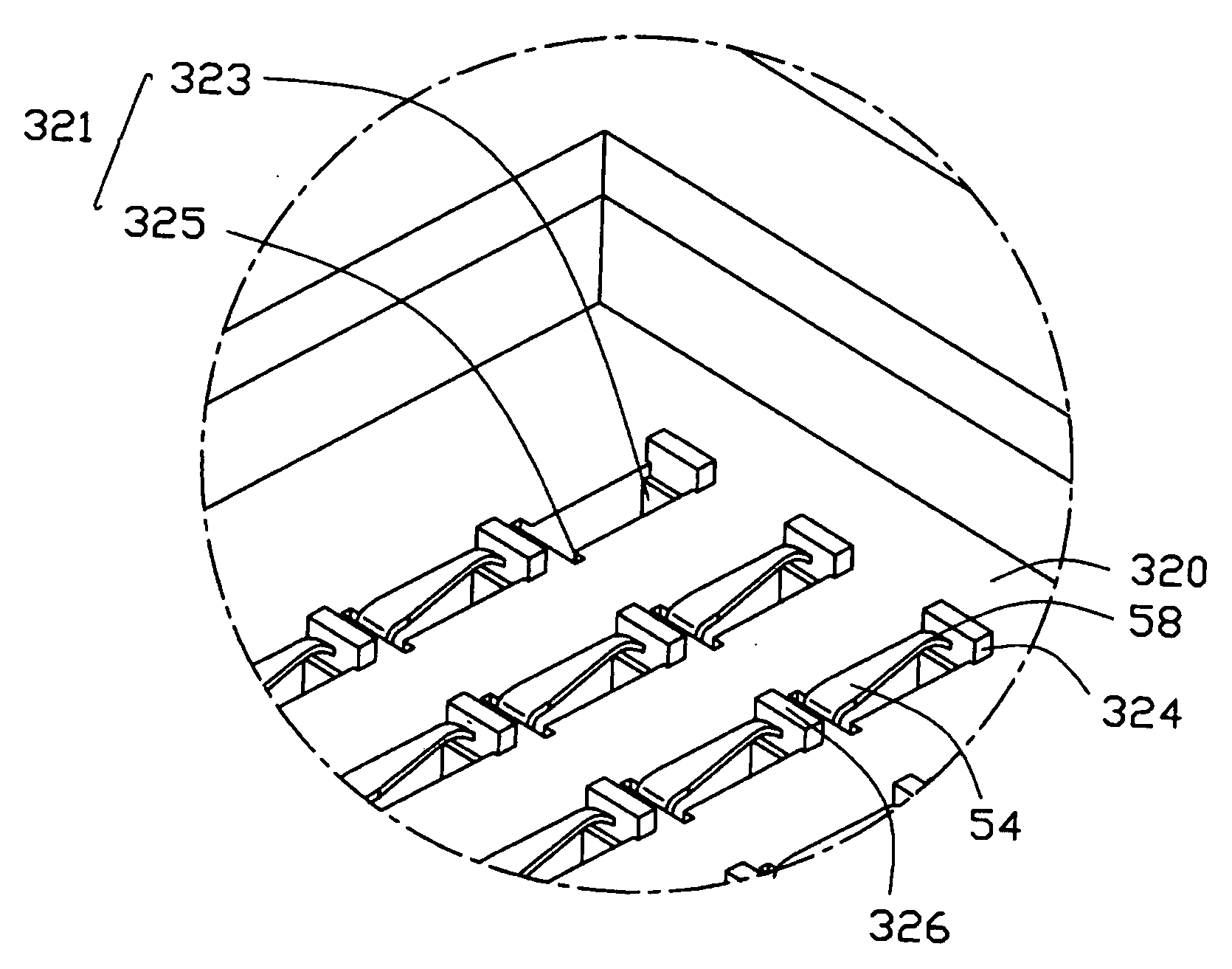
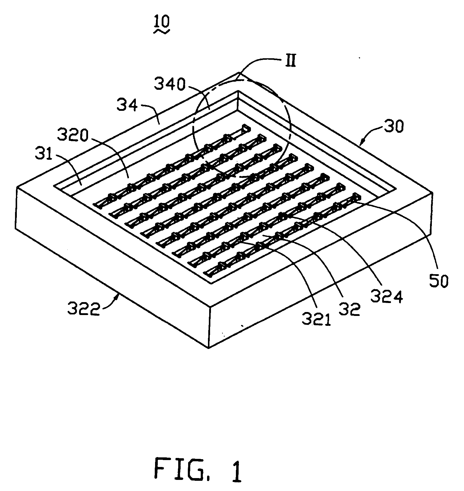
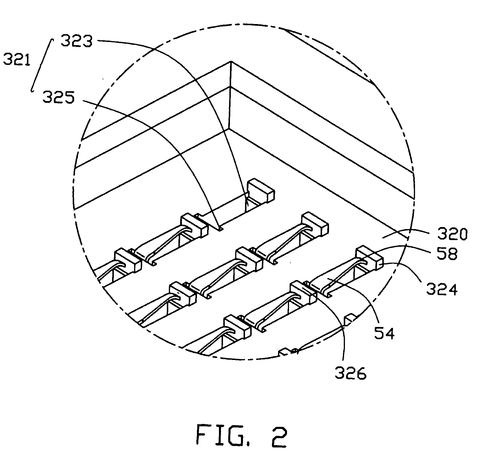
[0017] Referring to FIG. 1, an LGA connector 10 in accordance with a preferred embodiment of the present invention is provided for electrically connecting a CPU chip 80 to a PCB 90 (best seen in FIGS. 4 and 6). The LGA connector 10 may, of course, be applied in other environments such as for electrically interconnecting two PCBs and so on. The connector 10 comprises a rectangular insulative housing 30 and a plurality of terminals 50 received in the housing 30.

[0018] The housing 30 is configured with a bottom wall 32 and four side walls 34 extending upwardly from peripheries of the bottom wall 32. A receiving cavity 31 is defined between the bottom wall 32 and the side walls 34, for accommodating the CPU chip 3 therein. Guiding slant surfaces 340 are formed on the side walls 34 around a top mouth of the cavity 31, for facilitating insertion of the CPU package 90 into the cavity 31.

[0019] ...


PUM


Abstract

A land grid array connector (10) for electrically connecting a CPU package to a printed circuit board includes a housing (30) having a top surface (320) and a number of terminals received in passageways (31) of the housing. Each of the terminals has a retention portion (52), a spring arm (54) extending from the retention portion beyond the top surface. A contacting portion (58) is formed on a topmost part of the spring arm for electrically mating with a corresponding pad formed on a bottom of the CPU package. A plurality of protrusions (324) is formed on the top surface for protect the terminals from being accidental damaged, A common supporting surface (326) is formed cooperatively by the protrusions, above the contacting portion in a direction perpendicular to the top surface. This can protect the contacting portion of the terminal from being collided. As a result reliable electrical connection between the package and contacts of the land grid array connector is secured.

Description

BACKGROUND OF THE INVENTION [0001] 1. Field of the invention [0002] The present invention relates to electrical connectors, and more particularly to a land grid array (LGA) connector for electrically connecting an electronic package such as a CPU chip, to a circuit substrate such as a printed circuit board (PCB). [0003] 2. Description of the Prior Art [0004] Land grid array (LGA) electrical connectors are widely used in the connector industry for electrically connecting CPU chips to PCBs. A conventional LGA electrical connector is disclosed in U.S. Pat. No. 6,695,624. The electrical connector generally comprises an insulative housing and a plurality of electrical terminals received in the housing. Each terminal has a relatively long spring arm extending beyond outside the housing, for electrically mating with a corresponding pad on a CPU chip. However, the connector has a shortcoming that there is no protecting means for the terminals. When the connector is collided by an exterior o...

Claims


Application Information

Patent Timeline
IPC IPC(8): H01R12/00H01R12/04H01R12/16H01R13/24H05K7/10
CPCH01R13/2442H01R12/714H05K7/1061
Inventor MA, HAO-YUNSZU, MING-LUN
Owner HON HAI PRECISION IND CO LTD
Why Eureka
Try Eureka