Device for the electrical connection of contact pins to connecting pins with the terminal pins of a connector embodied by the device

a technology of a connector and a connector body, which is applied in the direction of coupling device connection, machine/engine, mechanical apparatus, etc., can solve the problems of coating material passing through the clearance in an undesired way, adverse electrical contact of the contact pin,

Active Publication Date: 2006-02-23
CONTINENTAL AUTOMOTIVE GMBH
View PDF8 Cites 4 Cited by
  • Summary
  • Abstract
  • Description
  • Claims
  • Application Information

AI Technical Summary

Benefits of technology

[0006] It is thus the object of this invention to provide a connecting device of the type mentioned above, in which a relatively exactly-defined position of the connecting device relative to a housing is guaranteed in a simple way.

Problems solved by technology

Establishing an electrical connection by means of the known connecting devices is problematical in so far as these devices are often not in an exactly defined position once fitted and, therefore, it is often necessary for them to also be adjusted manually.
Without such an adjustment of the position and orientation of the connecting device, the electrical contacting of the contact pins is adversely affected.
In addition, for a subsequent encapsulation of the connecting device (in the case of insufficient position accuracy) there is the further risk that coating material passes through the clearance in an undesired way, which in the case of an exactly defined position of the connecting device would be considerably smaller and therefore seal the opening.

Method used


Image

  • Device for the electrical connection of contact pins to connecting pins with the terminal pins of a connector embodied by the device
  • Device for the electrical connection of contact pins to connecting pins with the terminal pins of a connector embodied by the device
  • Device for the electrical connection of contact pins to connecting pins with the terminal pins of a connector embodied by the device

Examples


Embodiment Construction

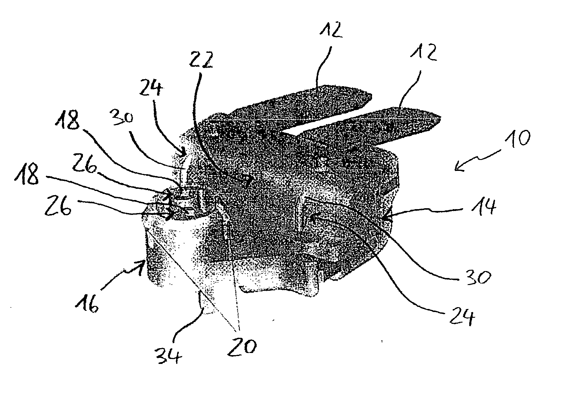
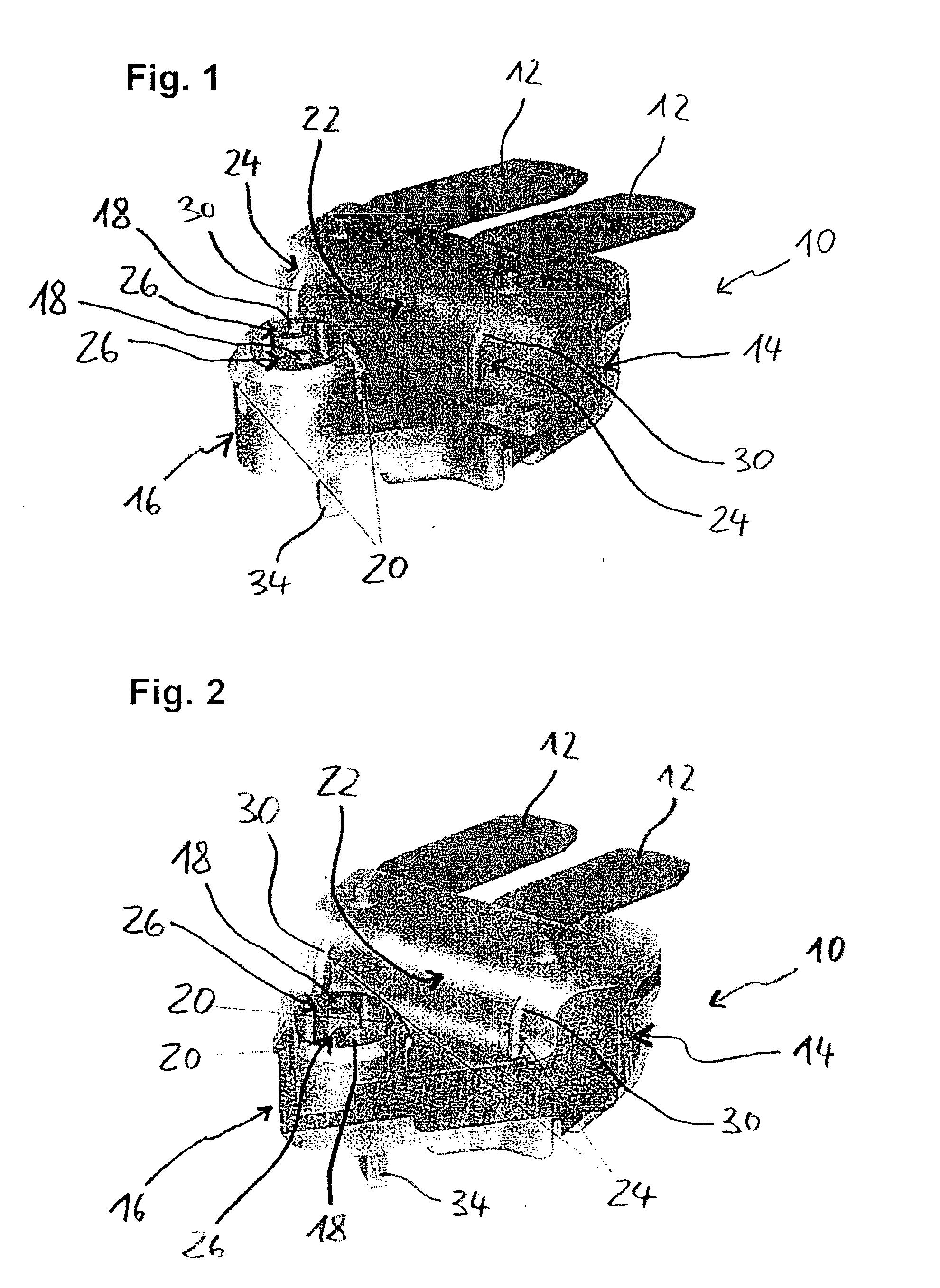
[0028]FIGS. 1 and 2 both show a contact tongue carrier indicated by the number 10 (connecting device) for the electrical connection of the contact pins of a piezoelectric actuator (not shown) with contact tongues 12 (terminal pins) which form an integral part of a plastic body 14 and together with a (not shown) plastic coating embodying a connector of a fuel injector.

[0029] In the example shown, the body 14 is a plastic part manufactured in one piece and has an insertion section 16 with an overall cylindrical contour which is embodied to make it suitable for axial insertion into an axial opening of a sleeve-type housing of the fuel injector and is provided with openings 18 to enable the contact pins of the piezoactuator to pass through, and also a contact surface 22 arranged offset to the side relative to the insertion section 16 and essentially extending tangentially at a distance from the insertion section 16. The contact surface 22 interoperates in the way described below, after...


PUM


Abstract

A device (10) has a contact surface (22) arranged laterally offset and essentially extending tangentially in relation to an insertion section (16), which, on introduction of the insertion section (16) into a housing opening, interoperates with a corresponding contact surface of the housing providing torsional stability, with the contact surface (22) of the connecting device (10) being embodied at areas of the contact surface tangentially opposite one another in each case with a plastic deformable contact surface projection (24) and/or the circumferential area of the insertion section having an annular closed area of the cylindrical surface on which a number of elastic, sprung, centering projections (20), projecting radially from the area of the cylindrical surface are provided which are arranged at intervals from one another around the circumference. This makes possible a functionally-optimized and tight-fitting interoperation between the corresponding contact surfaces.

Description

PRIORITY [0001] This application claims priority to U.S. Provisional Application 60 / 603,330 filed Aug. 20, 2004; German Application No. 10 2004 040 486.0 filed on Aug. 20, 2004 and European Application No. 04106075.7 filed Nov. 25, 2004.TECHNICAL FIELD OF THE INVENTION [0002] This invention relates to a device for the electrical connection of contact pins with the terminal pins of a connector embodied by the device. In addition, the invention relates to the use of such a connecting device. DESCRIPTION OF THE RELATED ART [0003] Such a connecting device in the form of a contact plate fitted onto two contact pins of a piezoelectric actuator is known from DE 197 15 487 A1. The known contact plate is made of an insulating plastic and is provided with openings for the projecting contact pins to pass through which are almost parallel to the longitudinal direction of the actuator. As a result, in the inside of the contact plate in each case, taking a contacting device at an opening as a sta...

Claims


Application Information

Patent Timeline
Patent Type & Authority Applications(United States)
IPC IPC(8): H01R3/08
CPCF02M51/005F02M63/0026H01R13/6315H01R13/631H01R13/405
Inventor SANFTLEBEN, EMANUELUNRUH, MARCUS
Owner CONTINENTAL AUTOMOTIVE GMBH
Why Eureka
Try Eureka