
Adaptive fault diagnosis of compressed test responses

a fault diagnosis and compressed test technology, applied in error detection/correction, instruments, computing, etc., can solve the problems of inaccurate fault diagnosis, often exceeding the capacity of automatic test equipment, test time, etc., and achieve the effect of increasing the hardware overhead of the cut and efficiently diagnosing failing scan cells during production testing

Active Publication Date: 2006-02-23
SIEMENS PROD LIFECYCLE MANAGEMENT SOFTWARE INC
View PDF76 Cites 23 Cited by
  • Summary
  • Abstract
  • Description
  • Claims
  • Application Information

AI Technical Summary

Benefits of technology

[0007] Many of the conventional fault diagnosis techniques for CUTs having compaction hardware require substantial additional hardware on the CUT or require multiple test sessions to produce useful results for diagnostic purposes. For these reasons, fault diagnosis has been viewed as impractical for production testing. Accordingly, there is a need for diagnostic techniques, especially indirect diagnostic techniques, that can be performed without substantially increasing the hardware overhead of the CUT and that can efficiently diagnose failing scan cells during production testing.

Problems solved by technology

For circuits that have embedded compression hardware, however, accurate fault diagnosis presents a formidable challenge.
Such sets, for example, often exceed the capacity of automatic test equipment (ATE) used to test today's multimillion-gate integrated circuits.
Moreover, due to the limited bandwidth between the circuit-under-test (CUT) and the ATE, the use of compressed test data and compressed test responses can help decrease test time, and thus the test cost.
For these reasons, fault diagnosis has been viewed as impractical for production testing.

Method used


Image

  • Adaptive fault diagnosis of compressed test responses
  • Adaptive fault diagnosis of compressed test responses
  • Adaptive fault diagnosis of compressed test responses

Examples


Embodiment Construction

General Considerations

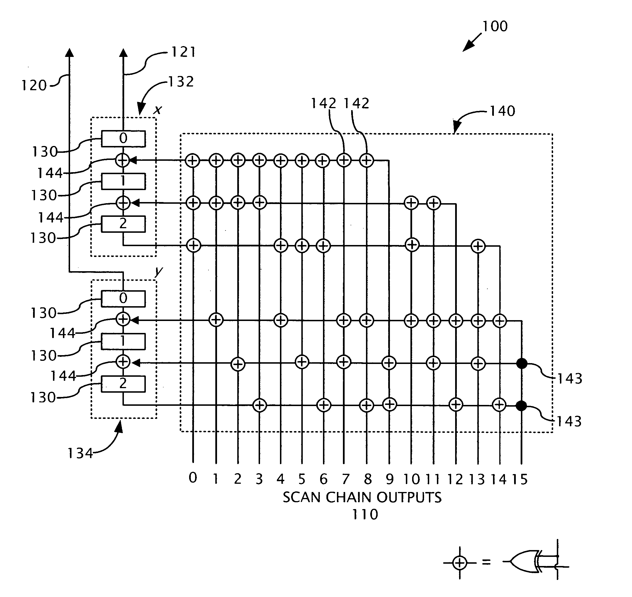
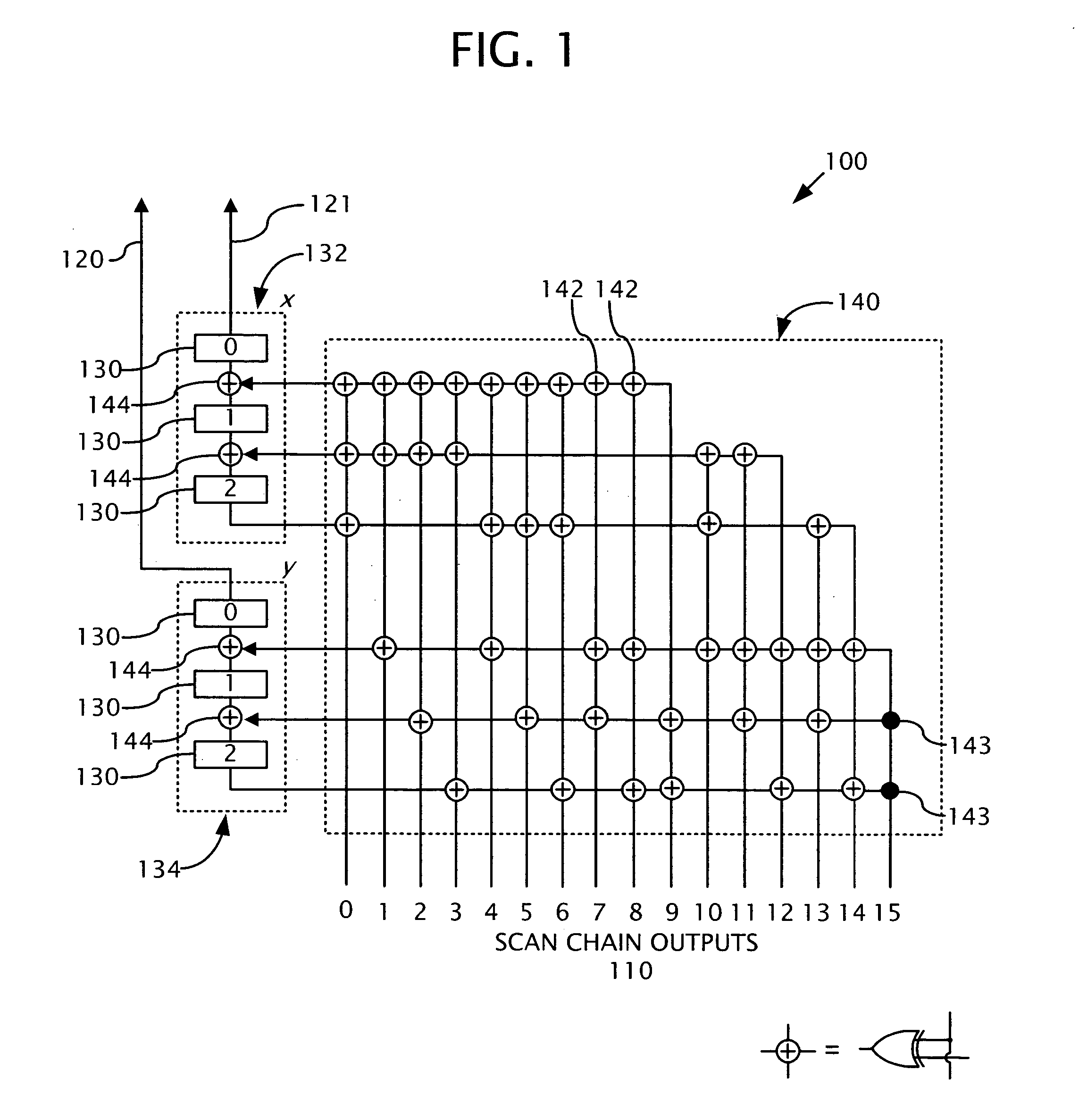
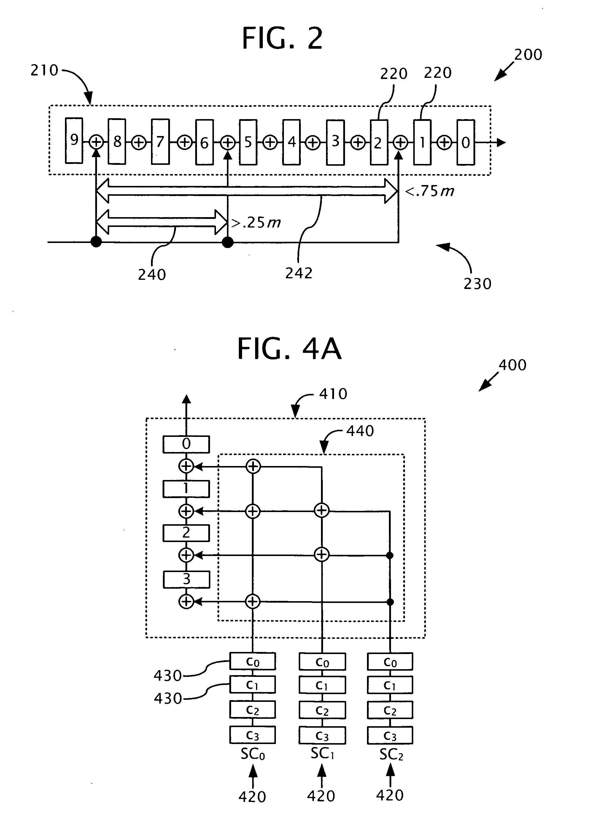
[0042] Disclosed below are representative embodiments of methods, apparatus, and systems for performing or enhancing fault diagnosis that should not be construed as limiting in any way. Instead, the present disclosure is directed toward all novel and nonobvious features and aspects of the various disclosed methods, apparatus, and systems, alone and in various combinations and subcombinations with one another. The disclosed technology is not limited to any specific aspect or feature described, or combination thereof, nor do the disclosed methods, apparatus, and systems require that any one or more specific advantages be present or problems be solved. Moreover, any of the methods, apparatus, and systems described herein can be used in connection with a wide variety of scan-based or partially-scan-based circuits that utilize embedded compression hardware.

[0043] Although the operations of some of the disclosed methods are described in a particular, sequential ord...


PUM


Abstract

Methods, apparatus, and systems for diagnosing failing scan cells from compressed test responses are disclosed herein. For example, in one nonlimiting exemplary embodiment, one or more signatures are received that indicate the presence of one or more errors in one or more corresponding compressed test responses. Scan cells in the circuit-under-test that caused the errors are identified by analyzing the signatures. In this exemplary embodiment, the analysis includes selecting a scan cell candidate that potentially caused an error in a compressed test response based at least partially on a weight value associated with the scan cell candidate, the weight value being indicative of the likelihood that the scan cell candidate caused the error. Tangible computer-readable media comprising computer-executable instructions for causing a computer to perform any of the disclosed methods are also provided. Tangible computer-readable media comprising lists of failing scan cells identified by any of the disclosed methods are also provided.

Description

CROSS-REFERENCE TO RELATED APPLICATIONS [0001] This application is a continuation-in-part of U.S. patent application Ser. No. 10 / 778,950, filed Feb. 13, 2004, which claims the benefit of U.S. Provisional Application No. 60 / 447,637, filed Feb. 13, 2003, and U.S. Provisional Patent Application No. 60 / 506,499, filed Sep. 26, 2003, all of which are hereby incorporated by reference. This application also claims the benefit of U.S. Provisional Patent Application No. 60 / 612,952, filed Sep. 24, 2004, which is also incorporated herein by reference.FIELD [0002] This application relates to testing integrated circuits. For example, this application discloses methods for analyzing compressed test responses in order to identify scan cells that captured error values after application of one or more test patterns. BACKGROUND [0003] The accurate diagnosis of faults is an increasingly important aspect of testing integrated circuits, especially in view of ever-increasing gate counts and shrinking feat...

Claims


Application Information

Patent Timeline
Patent Type & Authority Applications(United States)
IPC IPC(8): G01R31/28G06F11/00
CPCG01R31/31703G01R31/318536G01R31/318547G01R31/318566G11C2029/3202G01R31/31921G11C29/40G11C29/48G01R31/318583G06F11/00G01R31/28
Inventor RAJSKI, JANUSZMRUGALSKI, GRZEGORZPOGIEL, ARTURTYSZER, JERZYWANG, CHEN
Owner SIEMENS PROD LIFECYCLE MANAGEMENT SOFTWARE INC
Learn More