Method and apparatus for graphical presentation of firewall security policy

a firewall and security policy technology, applied in the field of computer networks, can solve the problems of more granular limit traffic between networks, network trust, damage limitation,

Inactive Publication Date: 2006-02-23
KYNDRYL INC
View PDF11 Cites 142 Cited by
  • Summary
  • Abstract
  • Description
  • Claims
  • Application Information

AI Technical Summary

Benefits of technology

[0021] The invention also resides in a system, method and computer program product for reporting improper settings in a firewall. A table including descriptions and security-risk severity ratings of a respective plurality of settings of t

Problems solved by technology

Because external entities are not under complete control of the enterprise and are open to unknown users who may not be trusted, these networks are not considered trusted.
Therefore, if the servers in the enterprise's DMZ are corrupted by a communication from another, untrusted network, the damage is limited.
Not only can a firewall deny traffic to and from networks, it can more granularly limit traffic between networks by limiting which hosts have access to communicate to or from network entities.
The limitation on the range of ports facilitates the handling of the requested service.
This makes the identification of the application using such a port difficult.
Some networks may not wish to accept certain types of ICMP messages.
For

Method used


Image

  • Method and apparatus for graphical presentation of firewall security policy
  • Method and apparatus for graphical presentation of firewall security policy
  • Method and apparatus for graphical presentation of firewall security policy

Examples


Embodiment Construction

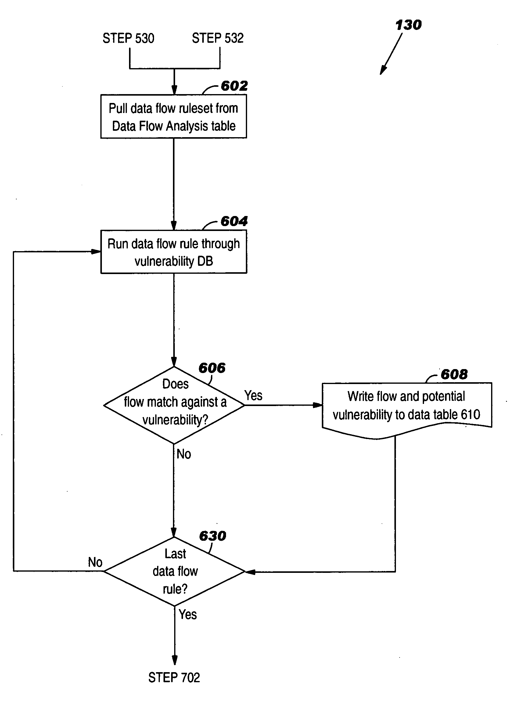
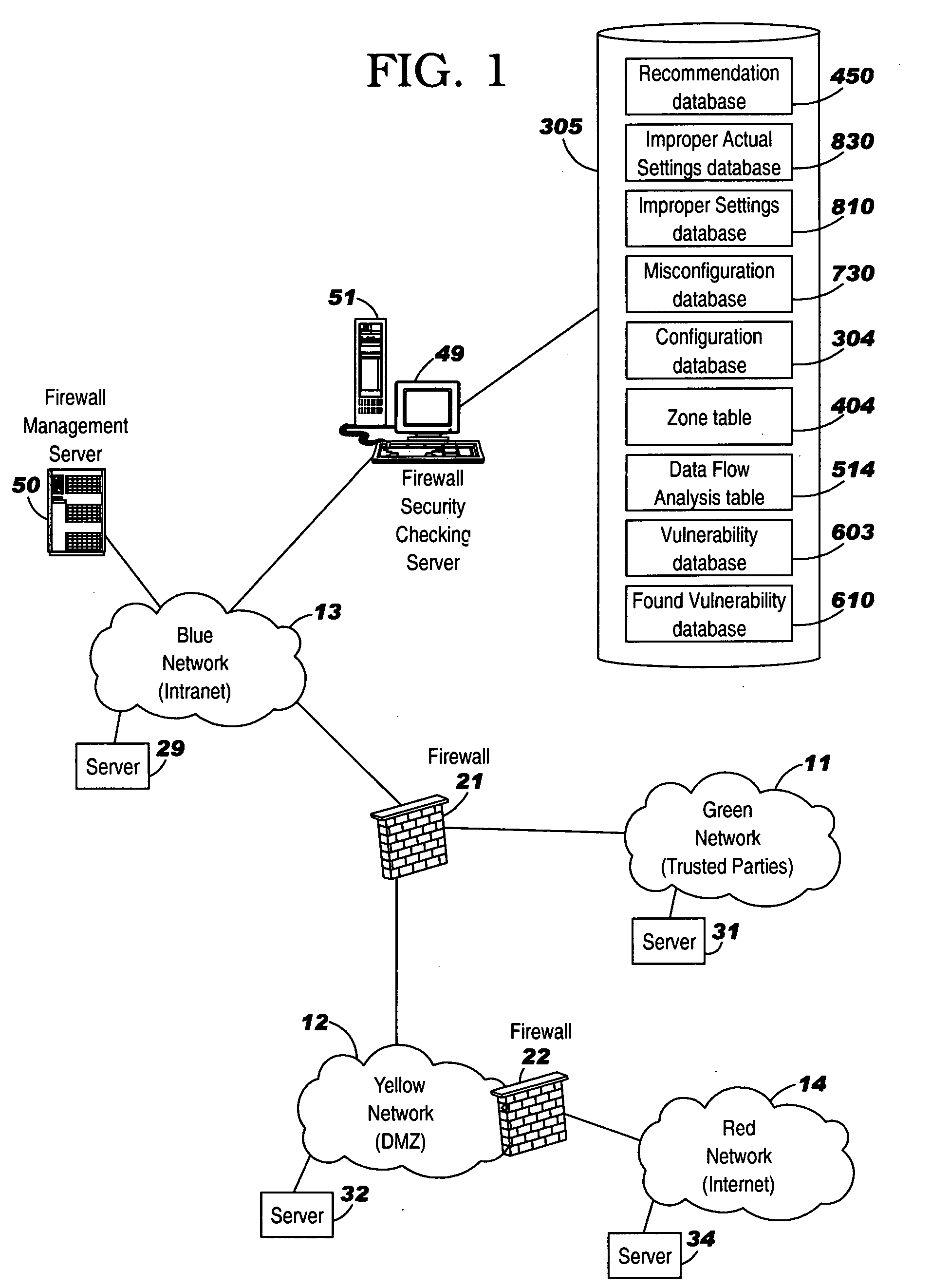
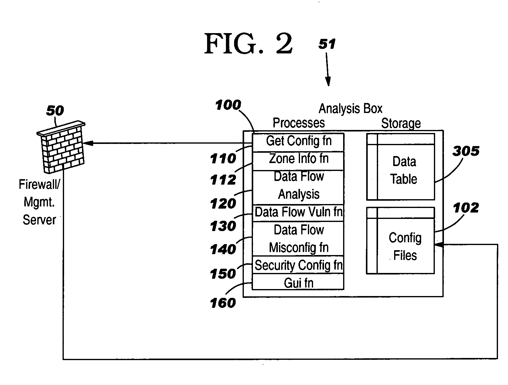
[0038] The present invention will now be described in detail with reference to the figures. FIG. 1 illustrates four networks 11-14. Network 13 has a firewall 21 which filters communications between network 13 and networks 11 and 12. There may be routers (not shown) within networks 11, 12 and 13. By way of example, network 13 is a secure, (“Blue”) enterprise intranet, network 12 is a semi-secure (“Yellow”) DMZ, and network 11 is semi-trusted (“Green”) network (from the point of view of network 13). By way of example, network 14 is an untrusted network such as the Open Internet, and is coupled to DMZ network 12 via another firewall 22 of DMZ network 12. However, the present invention can be used with a wide variety of networks. Network 13 comprises a firewall management computer 50 which manages firewall 21. The management functions include authorization, logging, and remote administration. Network 13 also comprises a firewall security checking server 51 which is responsible for check...


PUM


Abstract

A graphical representation of the firewall and a network coupled to the firewall is generated and displayed. A number of an inbound port of the network is displayed. An arrow adjacent to the port number pointing toward the network is displayed to indicate that a communication is permitted to the port. The port number and the arrow are located between an icon for the network and an icon for the firewall. A port number of a destination of a communication originating from the network is displayed. Also, another arrow adjacent to the destination port number pointing toward the firewall is displayed to indicate that a communication is permitted to the destination port number. The destination port number and the other arrow are located between an icon for the network and an icon for the firewall. A table including definitions of a plurality of rules is generated and displayed. Each of the definitions includes entries for a source IP address and destination IP address of a permitted but vulnerable data flow. The source IP address and destination IP address entries are color coded to indicate security levels of respective source and destination networks. Another table includes definitions of a misconfigured data flow, and entries for a source IP address and destination IP address of the misconfigured data flow. The source IP address and destination IP address are color coded to indicate security levels of respective source network and destination network.

Description

BACKGROUND OF THE INVENTION [0001] The invention relates generally to computer networks, and deals more particularly with a technique to graphically present data flows, vulnerabilities and misconfigurations in a firewall. [0002] To provide security, there are separate networks with security controls between each network. This enables an enterprise network to house confidential data separately from publicly available data, to separate financial networks from service networks, etc. All of these design considerations provide confidentiality, integrity and availability. Because external entities are not under complete control of the enterprise and are open to unknown users who may not be trusted, these networks are not considered trusted. Typically, an enterprise intranet is considered known and trusted because it houses internal communications within the enterprise. While this intranet communicates with an external network environment either to transmit or receive data communications, ...

Claims


Application Information

Patent Timeline
IPC IPC(8): G06F15/16
CPCH04L63/02H04L67/36H04L63/1433H04L67/75
Inventor ANDERSON, BROOKE MADSENBUNN, WILLIAM C.KARNES, MARYLIEBERMAN, SARAH M.WILCZEK, MIRA E.
Owner KYNDRYL INC
Why Eureka
Try Eureka