Dip molded wire connector

a technology of dip molded wire and connector, which is applied in the manufacture of connection end caps, contact member manufacturing, printed circuit manufacturing, etc., to achieve the effect of enhancing impact resistan

Inactive Publication Date: 2006-03-02
THE PATENT STORE
View PDF23 Cites 9 Cited by
  • Summary
  • Abstract
  • Description
  • Claims
  • Application Information

AI Technical Summary

Benefits of technology

[0012] A twist-on-connector with a dip-molded housing and a method for forming a twist-on wire connector with a dip-molded housing. To dip-mold a covering or housing on a twist-on wire connector either a mandrel carrying a twist-on wire coil, a mandrel having the shape of a spiral coil or a twist-on wire connector are dipped into a bath of an insitu solidifiable dip-moldable material such as liquid plastic. The dip-moldable material solidifies to form a dip-molded shell having enhanced impact resistance. In a further embodiment an end portion of a mandrel is allowed to be partially covered with dip-moldable material to enable the in situ formation of an integral cover on the housing of the wire connector.

Problems solved by technology

While these inventions are for the purposes of providing a soft grip they do not address the problem of making the twist-on wire connector with enhanced impact resistance.

Method used


Image

  • Dip molded wire connector
  • Dip molded wire connector
  • Dip molded wire connector

Examples


Embodiment Construction

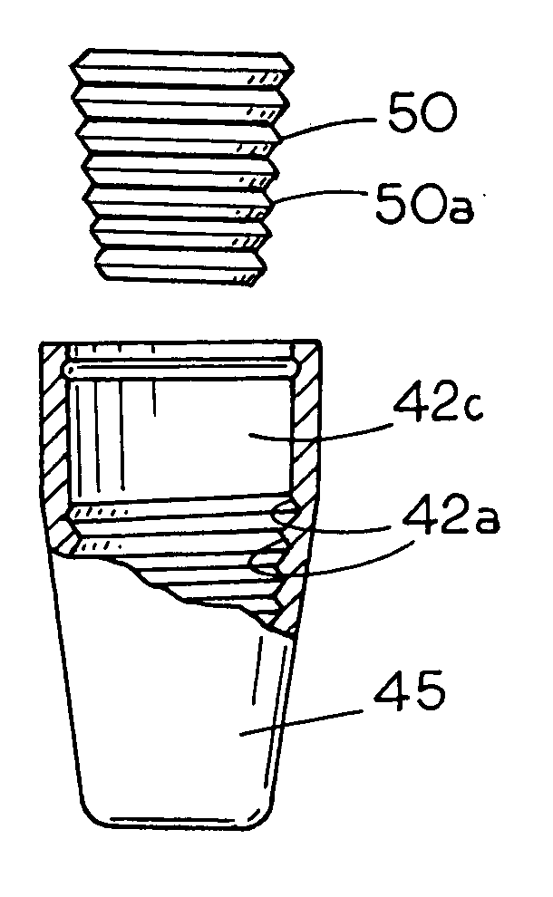
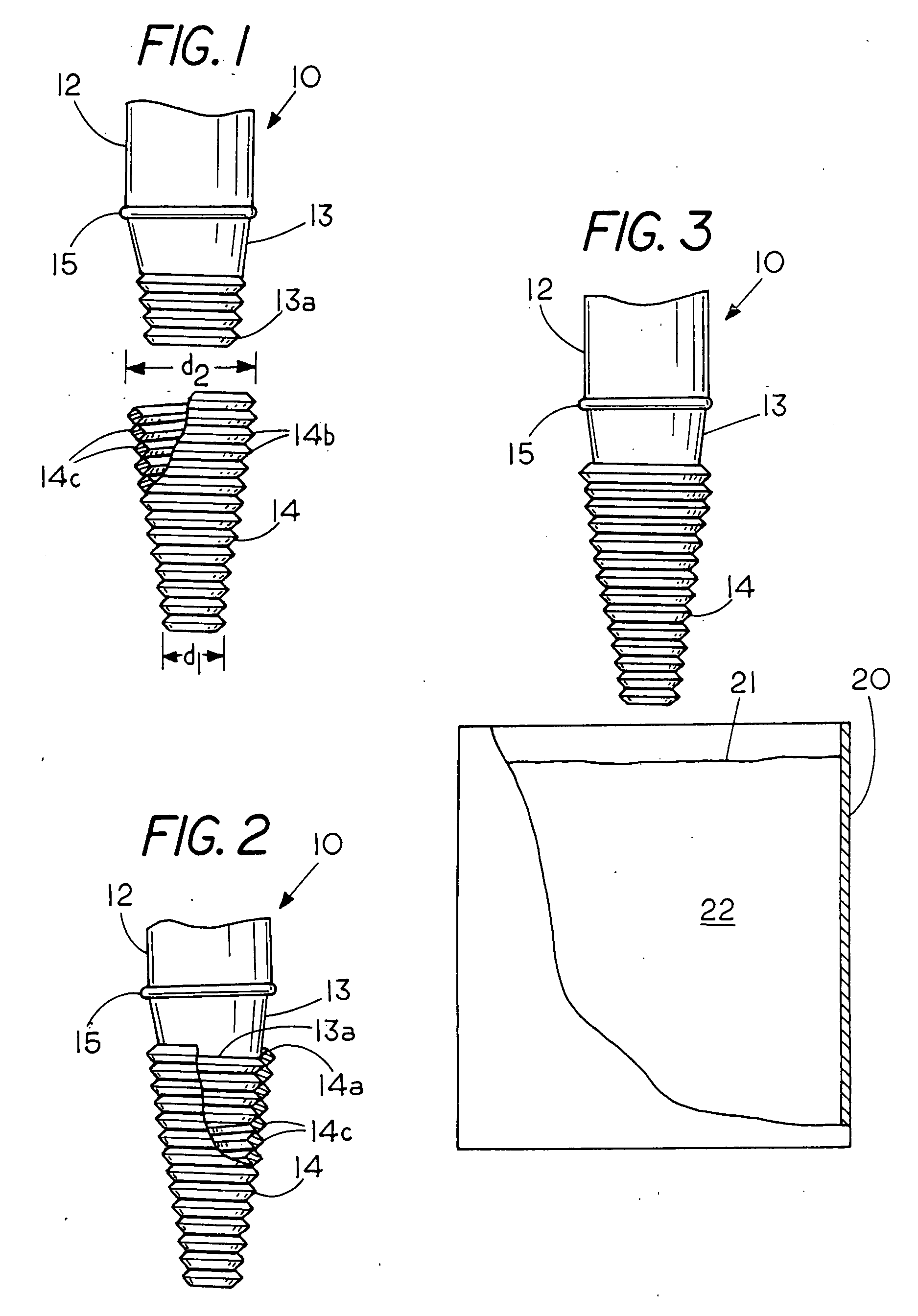
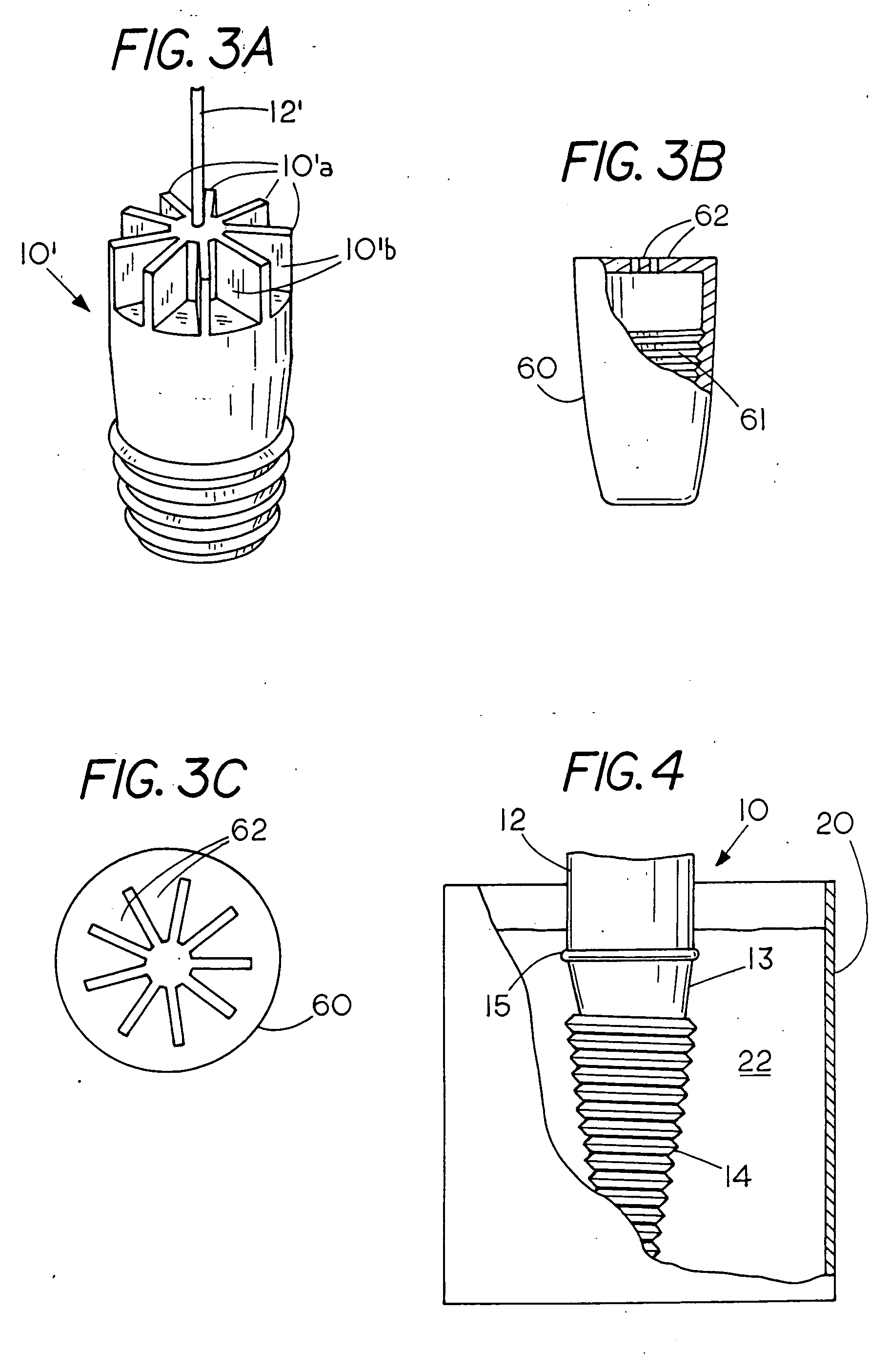
[0030]FIG. 1 is an elevation view of a mandrel 10 having a hanger bar 12 for raising and lower the mandrel 10 into a vat of dip-moldable material such as a vat of liquid plastic 20. Mandrel 10 incudes an annular bead 15, that is, an annular cover forming ridge 15 on the mandrel 10 that extends radially outward around the top portion of cylindrical mandrel housing 13. Annular cover forming ridge 15 is used for those twist-on wire connectors that have a separate end cap that is secured to the housing 13. If no end cap is used or if a non-insertable end cap is used cover forming ridge 15 need not be used. Mandrel 10 terminates in a frusto conical tip having an exterior surface with a male spiral thread 13a. Positioned beneath mandrel 10 is a wire coil 14 that has an interior surface with a female spiral thread 14c and an exterior surface with a male spiral thread 14b. The wire coil 14 comprises a spiral threaded wire coil with a maximum diametrical top dimension d2 that is larger than ...


PUM

PropertyMeasurementUnit
thicknessaaaaaaaaaa
thicknessaaaaaaaaaa
thicknessaaaaaaaaaa

Abstract

A connector with a dip-molded housing and a method for forming a twist-on wire connector with a dip-molded housing. To dip-mold a covering or housing on a twist-on wire connector either a mandrel carrying a twist-on wire coil, a mandrel having the a shape of a spiral coil or a twist-on wire connector are dipped into a bath of an in situ solidfiable dip-moldable material such as liquid plastic. The dip-moldable solidified material solidifies to form a dip-molded shell on the wire connector.

Description

FIELD OF THE INVENTION [0001] This invention relates generally to wire connectors and more specifically to twist-on wire connectors having a dip-molded shell to provide enhanced impact resistance through in-situ formation of the dip-molded shell. In one embodiment the dip-molded shell carries a twist-on wire coil and in another embodiment the dip-molded shell encapsulates the exterior surface of a rigid housing of a twist-on wire connector. CROSS REFERENCE TO RELATED APPLICATIONS [0002] None STATEMENT REGARDING FEDERALLY SPONSORED RESEARCH OR DEVELOPMENT [0003] None REFERENCE TO A MICROFICHE APPENDIX [0004] None BACKGROUND OF THE INVENTION [0005] The concept of dip-molding coverings or hollow shells for tool handles to provide a soft hand grip is well known in the art. An example of dip-molding using a mandrel is shown in U.S. Pat. No. 4,695,241 wherein an internal passage is provided so that a hollow part can be dip-molded. Still another example of dip-molding to form an electrical...

Claims


Application Information

Patent Timeline
Patent Type & Authority Applications(United States)
IPC IPC(8): H01R43/00
CPCH01R4/22H01R43/24Y10T29/4922Y10T29/49204Y10T29/49208Y10T29/4914Y10T29/49117Y10T29/49194
Inventor KING, L. HERBERT JR.BELGERI, MICHAELKEEVEN, JAMES
Owner THE PATENT STORE
Why Eureka
Try Eureka