
Brace assembly for truss legs of offshore structures

Inactive Publication Date: 2006-03-02
OFFSHORE TECH DEVMENT PTE
View PDF5 Cites 13 Cited by
  • Summary
  • Abstract
  • Description
  • Claims
  • Application Information

AI Technical Summary

Benefits of technology

[0007] It is an object of the present invention to provide an improved design of a brace assembly for a support leg of an offshore structure.
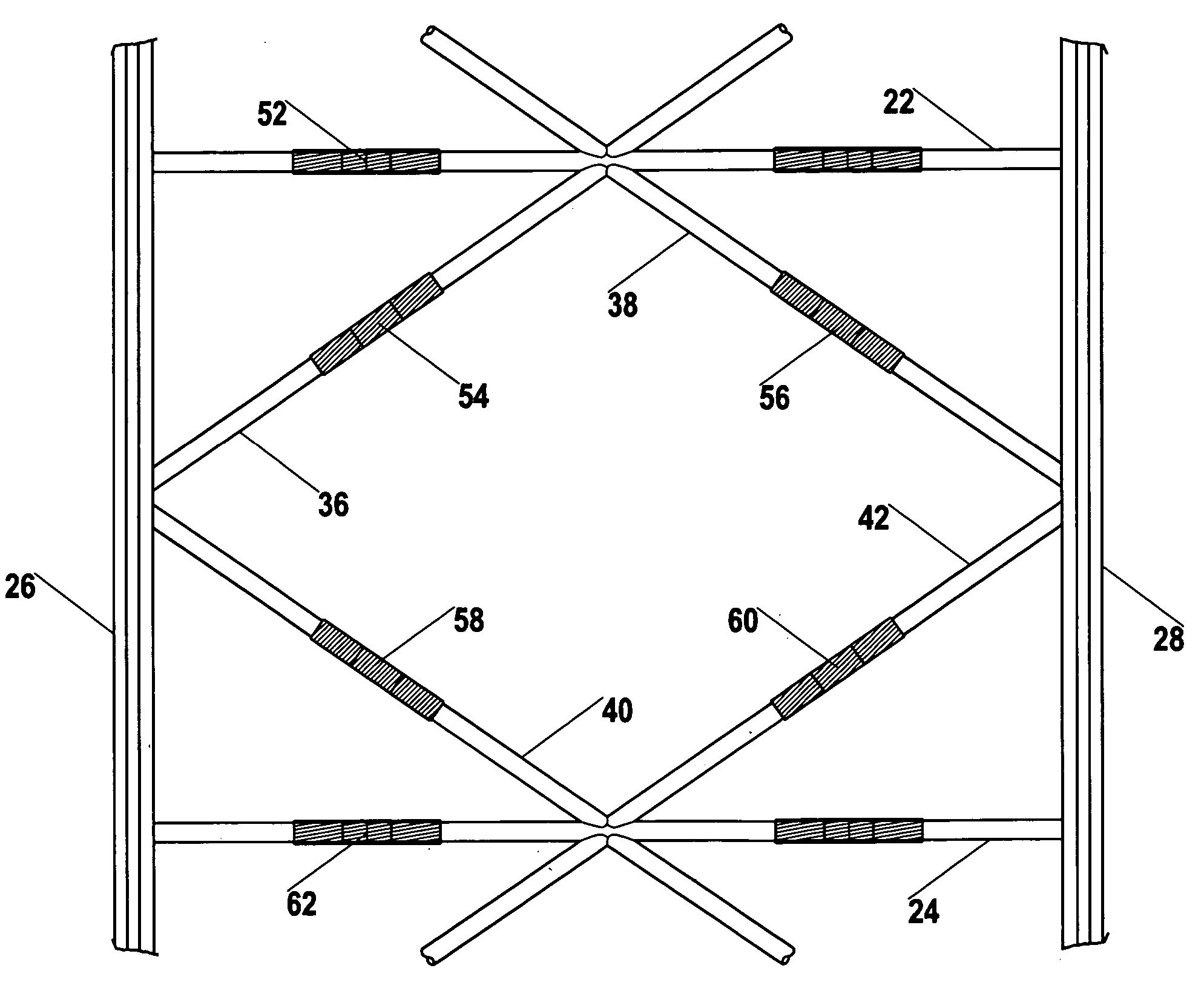
[0009] These and other objects of the invention are achieved through a provision of a reinforcing sleeve means for positioning over a pre-determined portion of a brace member and for increasing structural resistance of the brace member to horizontal moments. The reinforcing sleeve means is mounted and secured in a surrounding relationship about the exterior of the brace member. The thickness of the reinforcing sleeve means depends on the particular requirements of the load bearing capacity that must be achieved at the particular location of the overall structure.

Problems solved by technology

As the truss legs are composed of horizontal and diagonal braces, the braces tend to fail under compressive loads, which is built up due to the horizontal moment couple.
High compressive loads are undesirable as they result in buckling of the braces under severe environmental conditions.
This guide assembly is not efficient, as the generated high compressive loads located mainly between the upper and lower edge plates.
This constitutes a local failure within the system.
A premature local buckling of the brace assembly eventually occurs.
Due to the constraints in terms of weight and drag, it is not feasible to design the braces with heavy tubular sections.
With such designs, it is difficult and often costly to improve the strength of the braces due to the high cost involved in replacing all brace segments.
The expense associated with work stoppage as well as replacement of the damaged section and retrofitting the leg, plus the required manpower is often very high.

Method used


Image

  • Brace assembly for truss legs of offshore structures
  • Brace assembly for truss legs of offshore structures
  • Brace assembly for truss legs of offshore structures

Examples


Embodiment Construction

[0018] Reference will now be made to the following detailed description, taken in conjunction with the accompanying drawings, wherein like parts are designated by like numerals.

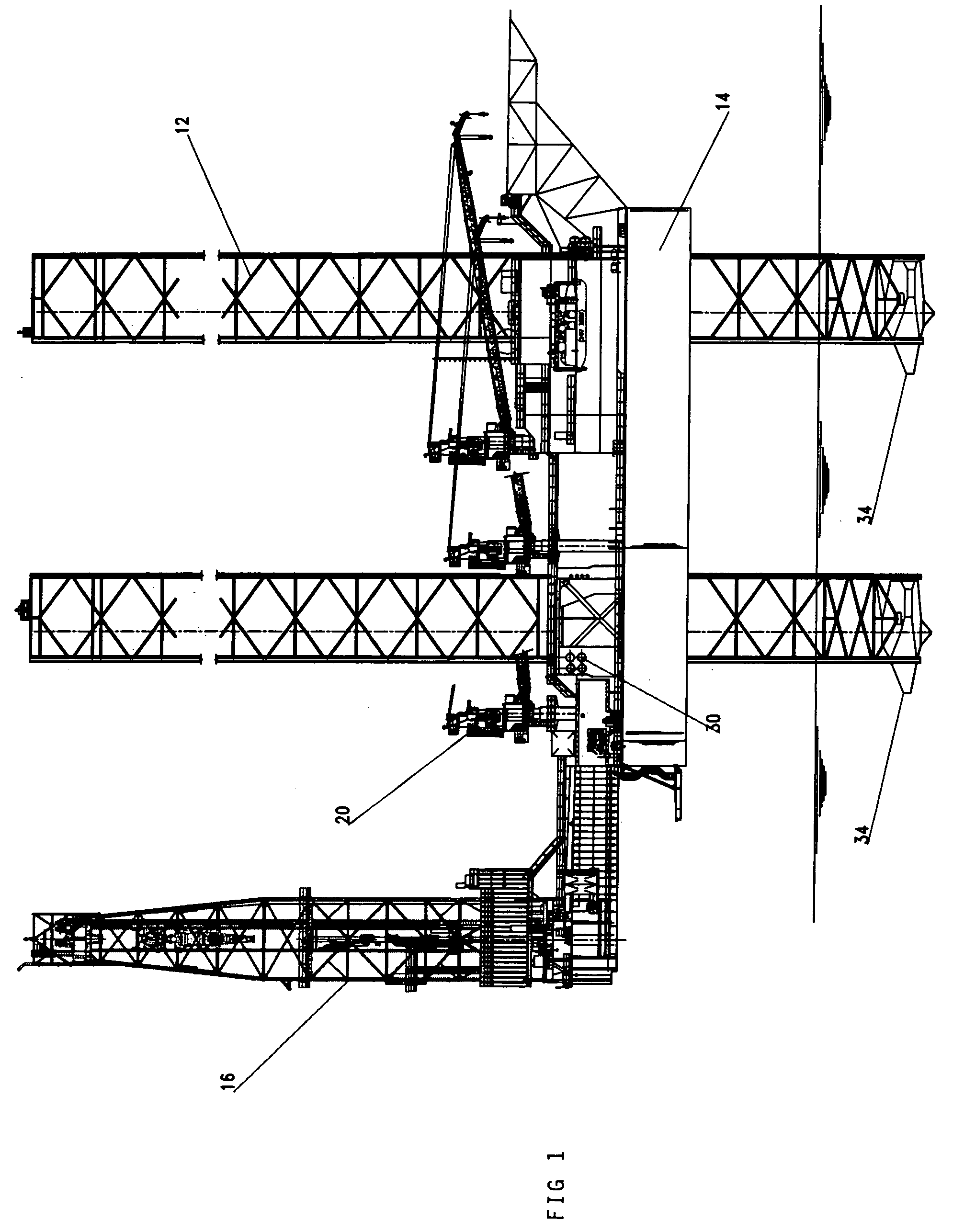
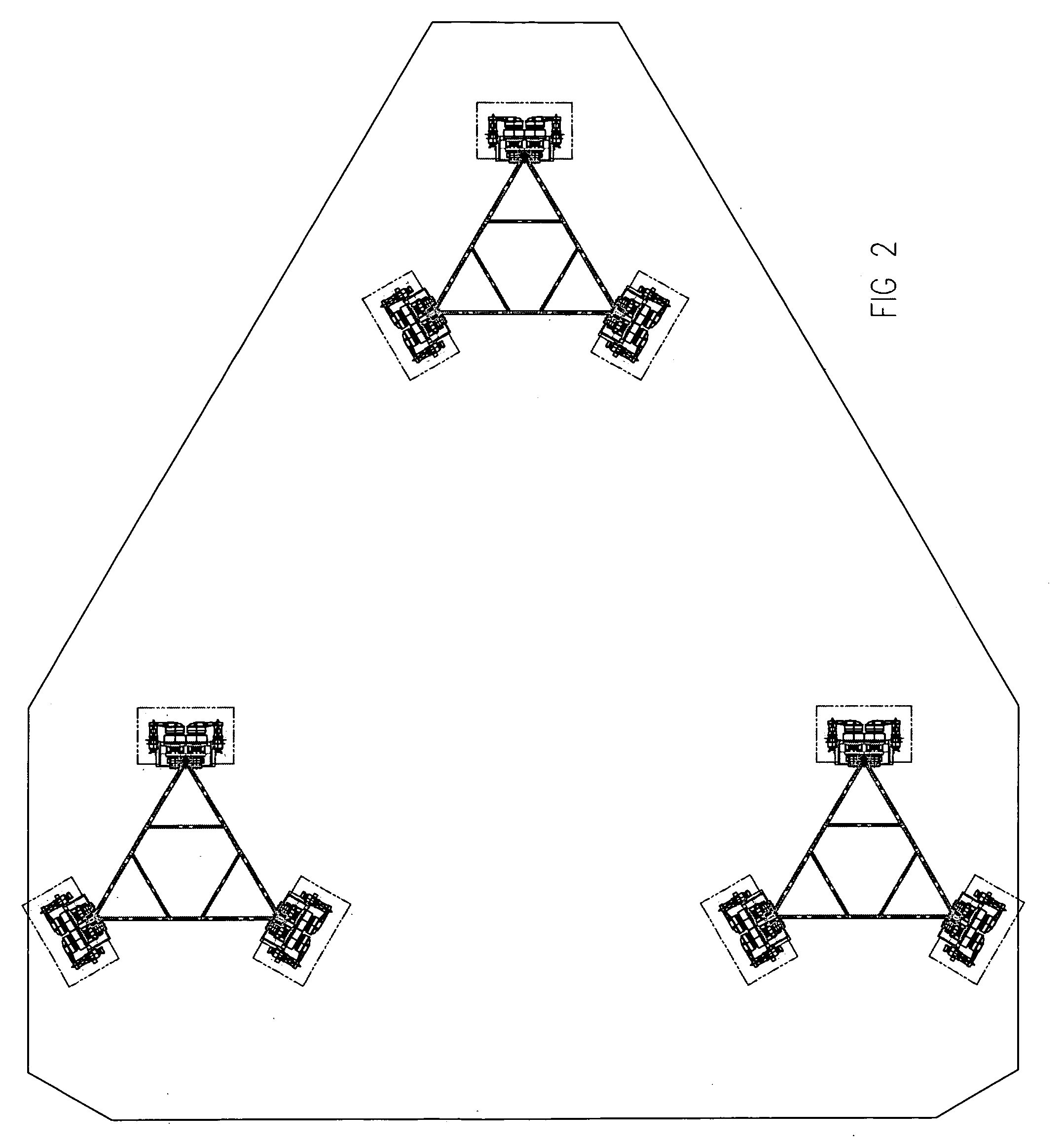
[0019]FIG. 1 shows a self-elevating jack-up unit. The jack-up unit is a mobile offshore structure that is used for mineral exploration and production. A typical jack-up unit is provided with a plurality of truss legs 12, which extend through openings in a floatable hull 14 of the jack-up unit. Although any number of legs may be used to support the hull 14, for illustration purposes, the jack-up rig shown in FIG. 1 has three such legs 12. The legs 12 are formed by a system of horizontal and diagonal braces.

[0020] As the legs 12 are “jacked,” the hull 14 is elevated above an anticipated wave action to support the offshore exploration and / or production operations. Conventional offshore structures, such as the jack-up unit, are equipped with a derrick 16 mounted on the hull 14. The derrick 16 may be also mounte...


PUM


Abstract

A brace assembly for truss legs of offshore structures is provided with a reinforcing sleeve mounted on the brace member in the portion of the brace member most prone to buckling under the force of horizontal moment acting on the brace member. The reinforcing sleeve surrounds the critical area of the brace member and provides additional load bearing capacity to the brace member. The reinforcing sleeve is made from a non-corrosive material having physical characteristics suitable to withstand the environmental forces in the location. The reinforcing sleeve may be installed at the shipyard when the offshore structure is manufactured or mounted on the existing rig by an easy retrofit not requiring towing of the offshore structure to the shipyard.

Description

BACKGROUND OF THE INVENTION [0001] The present invention relates to offshore structures, and more particularly, to a brace assembly for a truss leg. [0002] Leg-supported offshore structures are extensively used for mineral exploration and production. Convention truss legs comprise a system of horizontal and diagonal braces. The legs are raised or lowered by an elevating system, for instance a self-elevating jacking system that contains racks and pinions. In a typical system using triangular truss legs, there are a total of nine jacking assemblies, three assemblies per leg, One jacking assembly is mounted at each chord of the leg. Each jacking assembly unit has four to six pinions, which are house and supported on bearings. [0003] A series of guide plates is installed above and below the jacking mechanism. The guide system consists of upper guide plates, middle guide plates and lower wear plates. Gaps between guide plates and rack are pre-determined to ensure smooth transition in rai...

Claims


Application Information

Patent Timeline
IPC IPC(8): E04C3/02
CPCB63B35/4413E02B17/0004E04C3/291E04H12/10E04C2003/0413E04C2003/0447E04C2003/0495E04C2003/026
Inventor FOO, KOK SENGQUAH, CHIN KAU MATTHEW
Owner OFFSHORE TECH DEVMENT PTE
Learn More