Advanced friction stir welding tools

Inactive Publication Date: 2006-03-02
ARCONIC INC
View PDF19 Cites 53 Cited by
  • Summary
  • Abstract
  • Description
  • Claims
  • Application Information

AI Technical Summary

Benefits of technology

[0020] In another aspect, the present invention teaches an FSW tool having an axial tension member to reduce the damaging effects of cyclic bending moment loading on the pin as it is mov

Problems solved by technology

The disadvantage of this design is that it may be desirable to make the pin 22 of a material having preferred properties, which may not be needed for the shoulder 24, but which is very expensive.
Also, the material may be available only in small diameter fo

Method used


Image

  • Advanced friction stir welding tools
  • Advanced friction stir welding tools
  • Advanced friction stir welding tools

Examples


Example

[0044] In the discussion which follows, directional terms such as “upper”, “lower”, “top”, “bottom”, etc apply relative to welding setups oriented with the pin of the FSW tool at the bottom and the shank at the top. The terms “distal” and “proximal” are also used. Distal has the meaning of farthest from the shank of the FSW tool, proximal means nearer.

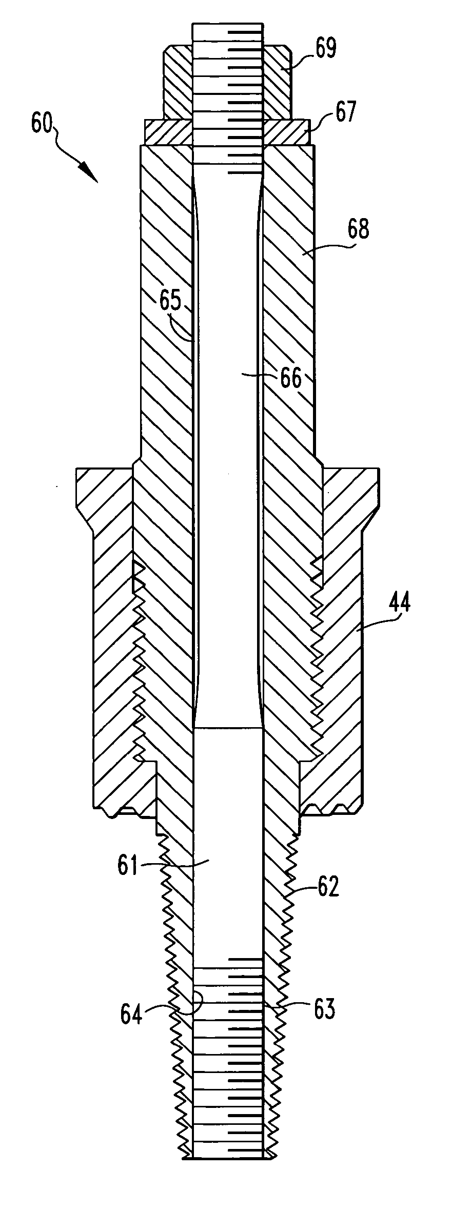
[0045] The present invention eliminates eccentricities between the pin and shank of an FSW tool which would otherwise cause the pin to vibrate and have a reduced life. The concept also reduces or eliminates eccentricities between the pins and shoulders of composite type FSW tools

[0046] In order to eliminate the eccentricities and their adverse effect on tool life during FS welding with traditional composite tools, this invention teaches the concept of making the pin and shank out of one monolithic piece. The shoulder is threaded onto the shank-pin unit 50.

[0047]FIGS. 12 and 13 are illustrations of an FSW tool 40 according to the pre...


PUM

PropertyMeasurementUnit
Flow rateaaaaaaaaaa
Creep rateaaaaaaaaaa
Tensionaaaaaaaaaa

Abstract

A friction stir welding tool includes an integral shank-pin unit and a shoulder attached to the shank-pin unit.

Description

CROSS REFERENCE TO RELATED APPLICATION [0001] The present invention claims priority from the provisional patent application entitled “Advanced Friction Stir Welding Tools”, Application No. 60 / 605,960, filed on Aug. 30, 2004.FIELD OF THE INVENTION [0002] The present invention relates to friction stir welding and, more particularly, it relates to improved tools for friction stir welding. BACKGROUND OF THE INVENTION [0003] The Friction Stir Welding (FSW) process is a solid-state based joining process, which makes it possible to weld a wide variety of materials (Aluminum, Copper, Stainless Steels, etc.) to themselves and to weld various combinations (e.g. aluminum alloys 6xxx / 5xxx, 2xxx / 7xxx, etc.) to each other. The process is based on “plunging” a rotating FSW tool into the joining area. The rotating friction stir welding tool heats the workipiece(s) by friction, so the material becomes plasticized and flows around the axis of the tool due to shear caused by the tool. [0004]FIG. 1 sho...

Claims


Application Information

Patent Timeline
IPC IPC(8): B23K20/12
CPCB23K20/1255
Inventor STOL, ISRAELCOBES, JOHN W.
Owner ARCONIC INC
Why Eureka
Try Eureka