Non-visible radiation imaging and inspection

Active Publication Date: 2006-03-02
INT ELECTRONICS MACHINES
View PDF9 Cites 65 Cited by
  • Summary
  • Abstract
  • Description
  • Claims
  • Application Information

AI Technical Summary

Benefits of technology

[0011] The invention provides a non-visible radiation imaging system. Specifically, under the present invention, one or more images of an object can be obtained based on non-visible radiation of the object. Additionally, one or more visible light images can be obtained for the object. In the latter case, an object image can be generated based on the non-visible radiation image(s) and the visible light image

Problems solved by technology

However, to date, infrared imaging solutions have lagged in both resolution and cost as compared to visible

Method used


Image

  • Non-visible radiation imaging and inspection
  • Non-visible radiation imaging and inspection
  • Non-visible radiation imaging and inspection

Examples


Embodiment Construction

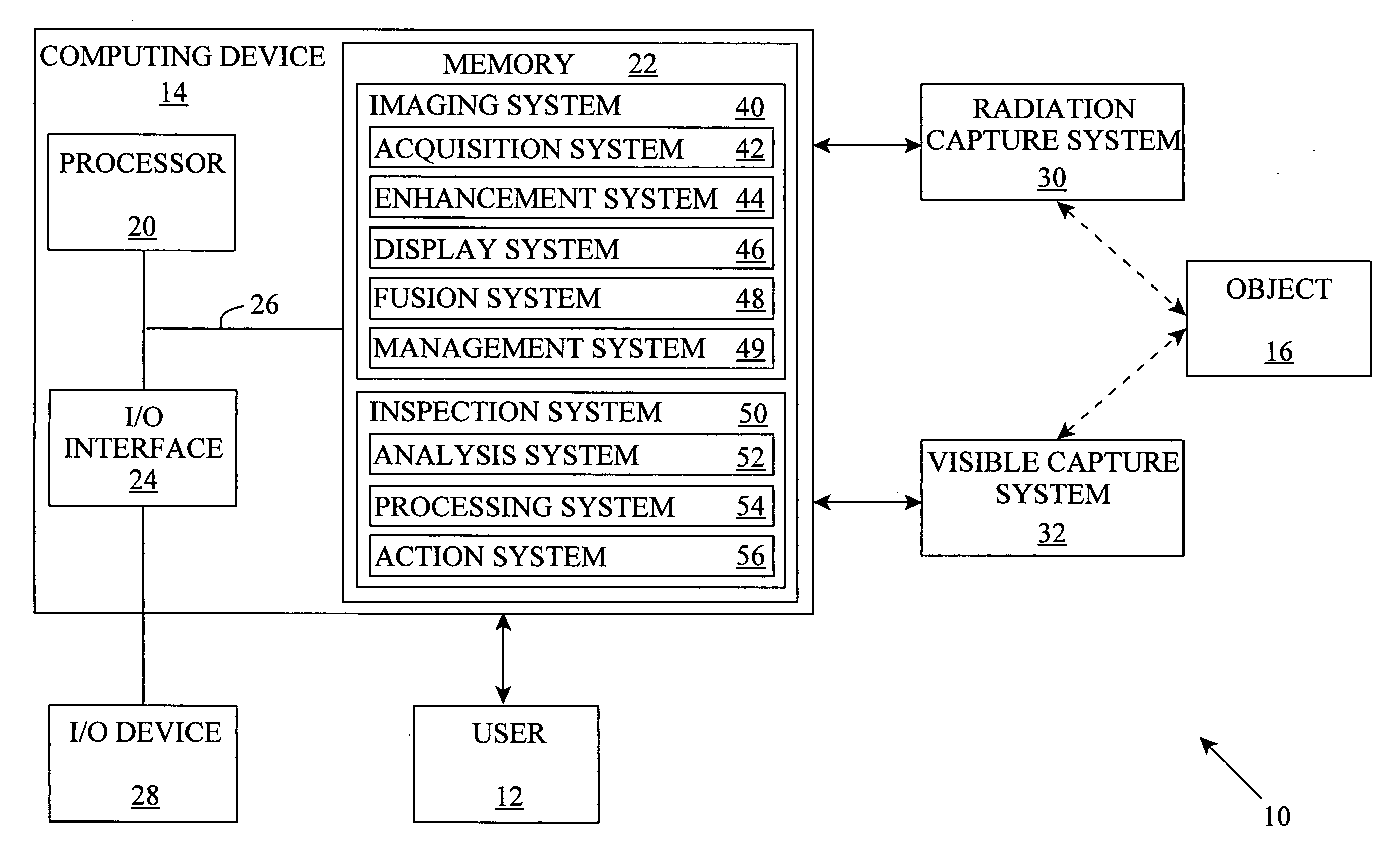
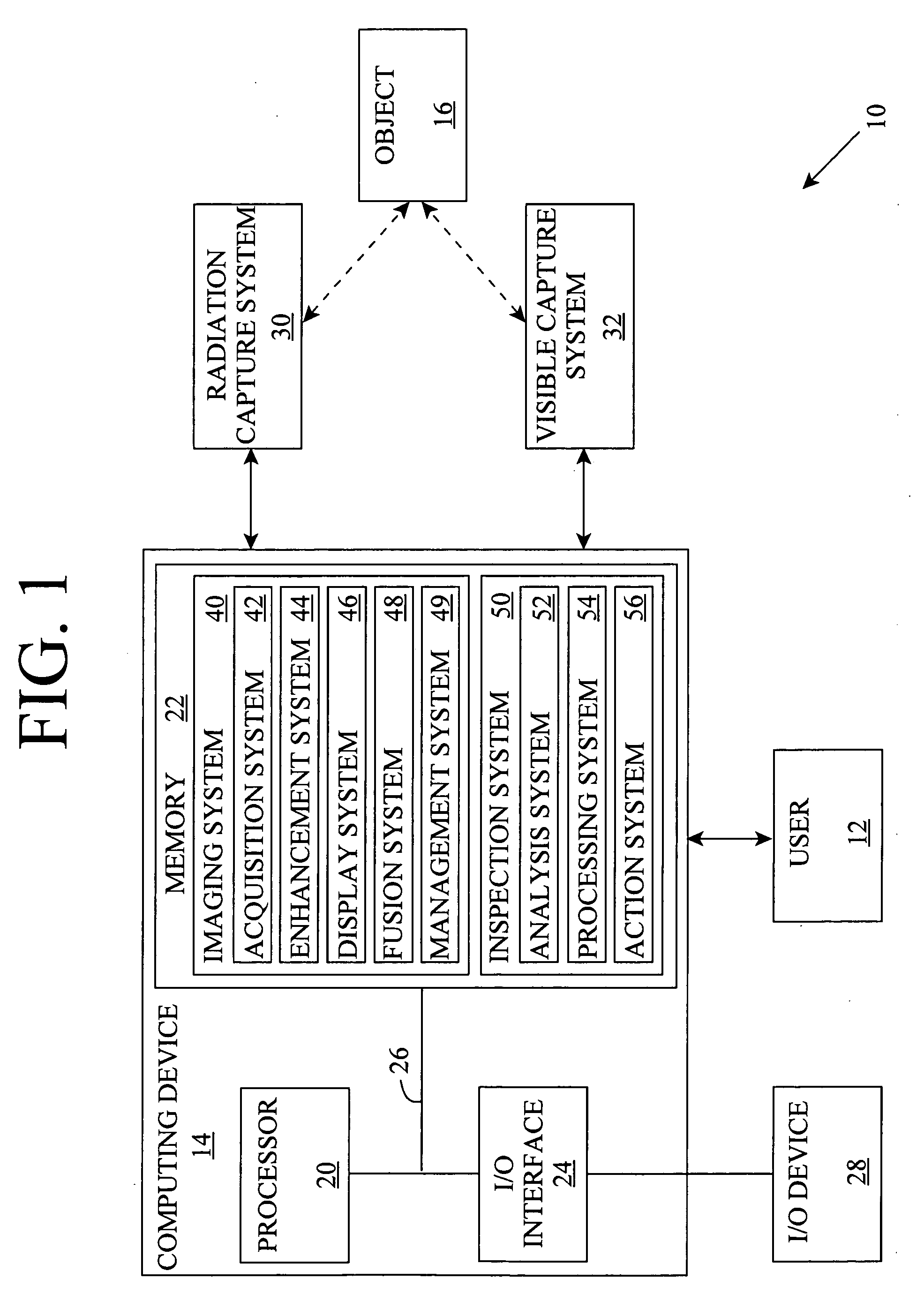
[0027] As indicated above, the invention provides a non-visible radiation imaging system. Specifically, under the present invention, one or more images of an object can be obtained based on non-visible radiation of the object. Additionally, one or more visible light images can be obtained for the object. In the latter case, an object image can be generated based on the non-visible radiation image(s) and the visible light image(s). In any event, the non-visible radiation image(s) can have a low resolution that is enhanced to increase the amount of resolution for the radiation image. The visible light image(s) and / or other data on the object can be used to generate the enhanced image. As a result, a lower resolution, and therefore lower cost, non-visible radiation imaging system can be used to obtain the desired imaging resolution.

[0028] The invention also provides a non-visible radiation inspection system and method. In particular, one or more of the images discussed above can be us...


PUM


Abstract

A non-visible radiation imaging system is provided in which an image is obtained based on non-visible radiation of an object. The image can be enhanced to increase its resolution. Additionally, the image can be combined with another image based on visible light for the object. Further, a non-visible radiation inspection system and method are provided that perform an inspection of the object using one or more of the images.

Description

REFERENCE TO PRIOR APPLICATION [0001] The current application claims the benefit of co-pending U.S. Provisional Application No. 60 / 603,548, filed on Aug. 24, 2004, which is hereby incorporated herein by reference.BACKGROUND OF THE INVENTION [0002] 1. Technical Field [0003] The invention relates generally to imaging non-visible radiation and / or visible light for an object, and to performing an inspection of the object using the non-visible radiation and / or visible light image(s). [0004] 2. Background Art [0005] Numerous imaging devices exist for generating images of objects based on electromagnetic radiation in the visible light spectral band. However, additional information on one or more attributes of many objects can be obtained from imaging electromagnetic radiation having wavelengths that fall above and / or below visible light. For example, infrared light (e.g., thermal radiation) can be imaged to determine the temperature characteristics of the object. Other radiation spectra ha...

Claims


Application Information

Patent Timeline
IPC IPC(8): G01J5/00
CPCG01J1/0219G01J1/0233G01J1/42G01J5/02G06T3/4061G01J5/08G01J5/0846G01J2005/0077G01J5/025
Inventor MIAN, ZAHID F.MULLANEY, JEREMY C.SPOOR, RYK E.
Owner INT ELECTRONICS MACHINES
Why Eureka
Try Eureka