Torque-limited electrical connector

a technology of electrical connectors and torque-limited connectors, which is applied in the direction of screw, load-modifying fasteners, coupling device connections, etc., can solve the problems of user over-torqueing the connector, lack of assurance that the connector is tightened to the required torque without,

Active Publication Date: 2006-03-02
CAES SYST LLC
View PDF6 Cites 19 Cited by
  • Summary
  • Abstract
  • Description
  • Claims
  • Application Information

AI Technical Summary

Benefits of technology

[0005] A coupling mechanism is provided. The coupling mechanism includes a bushing assembly adapted to establish a coupling when rotated, a housing that is rotatable when torque is applied to the housing, a torque-limit member positioned between the housing and the bushing assembly such that when the torque-limit member is in a positive-lock state, the housing and bushing assembly rotate jointly upon the application of torque until a predefined torque level is attained. A compressible member is included that engages the torque-limit member to define through frictional resistance of moving parts and parts geometry a predefined torque level. The torque-limit member switches from the positive-lock state to a ratchet state when the predefined torque level is attained. When the torque-limit member is in the ratchet state, the housing rotates relative to the bushing assembly.

Problems solved by technology

In certain applications, the connectors are exposed to very adverse operating conditions, such as wide ranging temperatures, intemperate weather, vibration and the like.
However, even with a torque wrench, the user may over torque the connector.
Thus, the method lacks assurance that the connector is tightened to the required torque without over tightening.

Method used


Image

  • Torque-limited electrical connector
  • Torque-limited electrical connector
  • Torque-limited electrical connector

Examples


Embodiment Construction

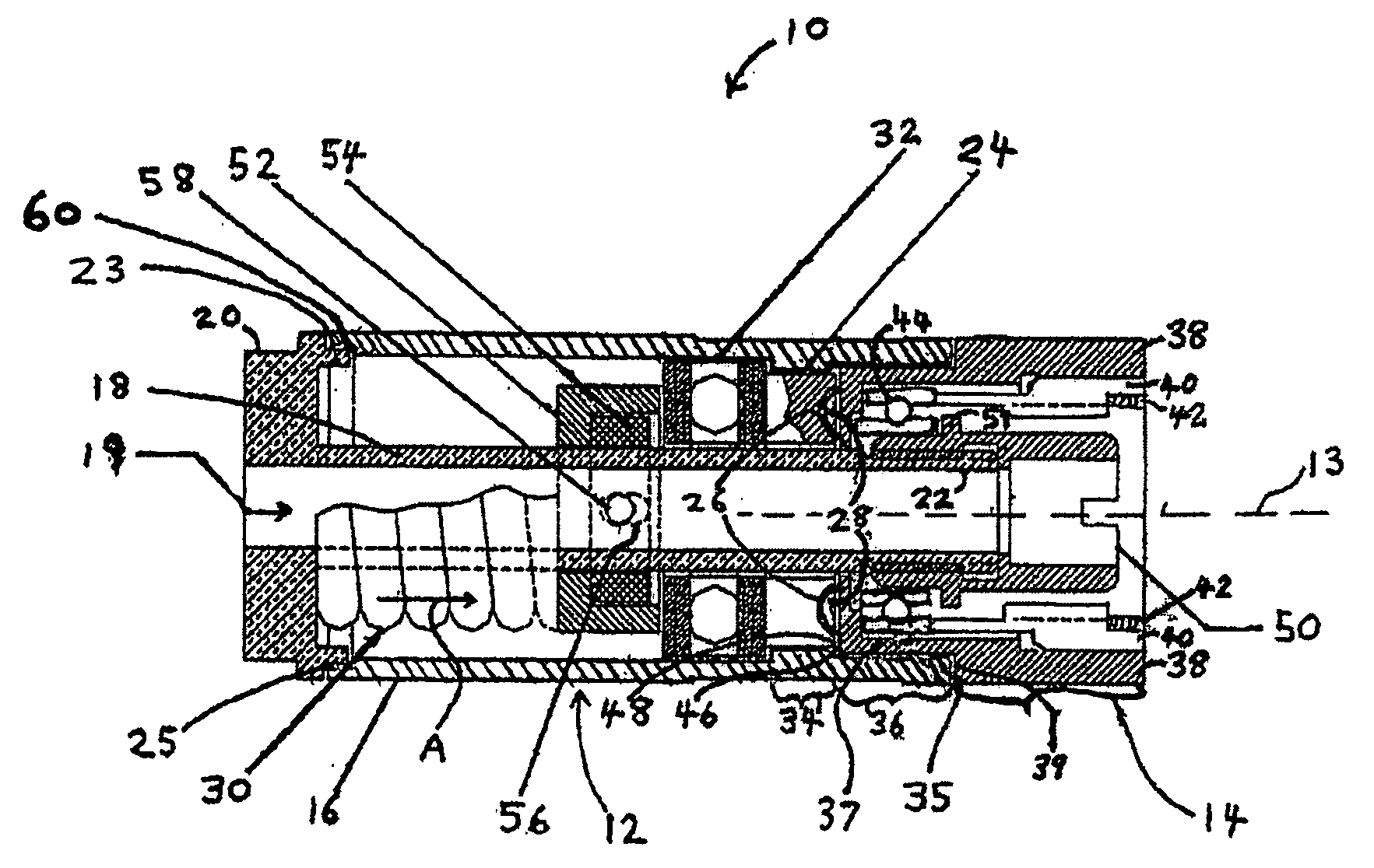
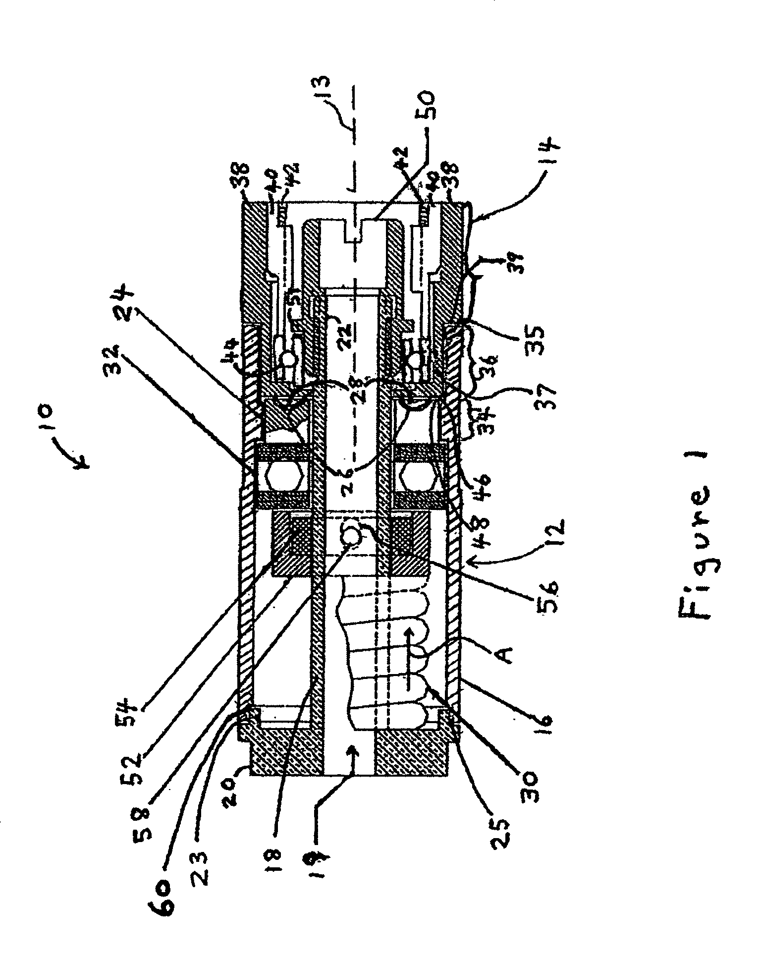
[0018]FIG. 1 illustrates a side section view of an electrical connector 10. Electrical connector 10 provides a coupling mechanism for connecting an electrical cable to electronic equipment. The electrical connector 10 includes two main assemblies, a housing 12 and a bushing assembly 14. The bushing assembly 14 is an example of a body adapted to establish a coupling to mating electrical equipment when rotated. The housing 12 is rotatably joined to the bushing assembly 14. The housing 12 is rotatable by the application of torque, such as to an intermediate section 34 of a sleeve 16 by a user's hand or tool. A torque-limit member, such as a ratchet plate 24 and protrusions 28, rotatably interconnects the housing 12 and the bushing assembly 14 when the ratchet plate 24 is in a positive-lock state.

[0019] When the ratchet plate 24 is in a positive-lock state, the housing 12 and the bushing assembly 14 turn together (or jointly) about a rotation axis 13 when torque is applied to the inter...


PUM


Abstract

A coupling mechanism is provided. The coupling mechanism includes a bushing assembly adapted to establish a coupling when rotated, a housing that is rotatable when torque is applied to the housing, a torque-limit member positioned between the housing and the bushing assembly such that when the torque-limit member is in a positive-lock state, the housing and bushing assembly rotate jointly upon the application of torque until a predefined torque level is attained. A compressible member is included that engages the torque-limit member to define through frictional resistance of moving parts and parts geometry a predefined torque level. The torque-limit member switches from the positive-lock state to a ratchet state when the predefined torque level is attained. When the torque-limit member is in the ratchet state, the housing rotates relative to the bushing assembly.

Description

BACKGROUND OF THE INVENTION [0001] This invention relates generally to electrical connectors and more particularly, to electrical connectors having a threaded coupling. [0002] A variety of electrical connectors have been proposed to interconnect electrical cables with equipment in a simple and reliable fashion. In certain applications, the connectors are exposed to very adverse operating conditions, such as wide ranging temperatures, intemperate weather, vibration and the like. For example, the electronic equipment in an aircraft is connected to numerous electrical cables. It is very important that the electrical connectors remain securely coupled to the equipment and not become accidentally unplugged or damaged over their specified life expectancy and environment. [0003] Some electrical cable connectors include threaded bushings that are coupled to a threaded male receptacle on the electronic equipment. The bushings are free spinning to allow the cable connector to turn, when being...

Claims


Application Information

Patent Timeline
Patent Type & Authority Applications(United States)
IPC IPC(8): H02K5/00
CPCH01R4/56H01R35/04H01R13/622
Inventor LAU, MICHAEL ROBERTDE WILD, ERIC MICHEL
Owner CAES SYST LLC
Why Eureka
Try Eureka