Power converter apparatus and methods using output current feedforward control

a technology of output current and power converter, applied in the direction of power conversion systems, dc-dc conversion, instruments, etc., can solve the problems of large increase in input power and output voltage, circuits as complex, and detrimental effect on control circuit stability and dynamic response, so as to reduce the amount of correction and fast load transient response

Inactive Publication Date: 2006-03-02
LAMBDA AMERICAS
View PDF22 Cites 124 Cited by
  • Summary
  • Abstract
  • Description
  • Claims
  • Application Information

AI Technical Summary

Benefits of technology

[0007] Some embodiments of the present invention arise from a realization that output current feed forward can be used in a boost converter to provide very fast load transient response and significantly reduce the amount of correction that has to be provided by the feedback loop. Furthermore, boost converter control circ...

Problems solved by technology

As the input current of such a converter is generally proportional to its input voltage, an increase in the input voltage will generally cause an increase in the input current, which may result in a large increase in the input power and the output voltage.
This gain variation may have a detrimental effect on the stability and dynamic response of the control circuit.
Control circuits without an explicit current waveform reference typically do not require input voltage information, so adding circui...

Method used


Image

  • Power converter apparatus and methods using output current feedforward control
  • Power converter apparatus and methods using output current feedforward control
  • Power converter apparatus and methods using output current feedforward control

Examples


Embodiment Construction

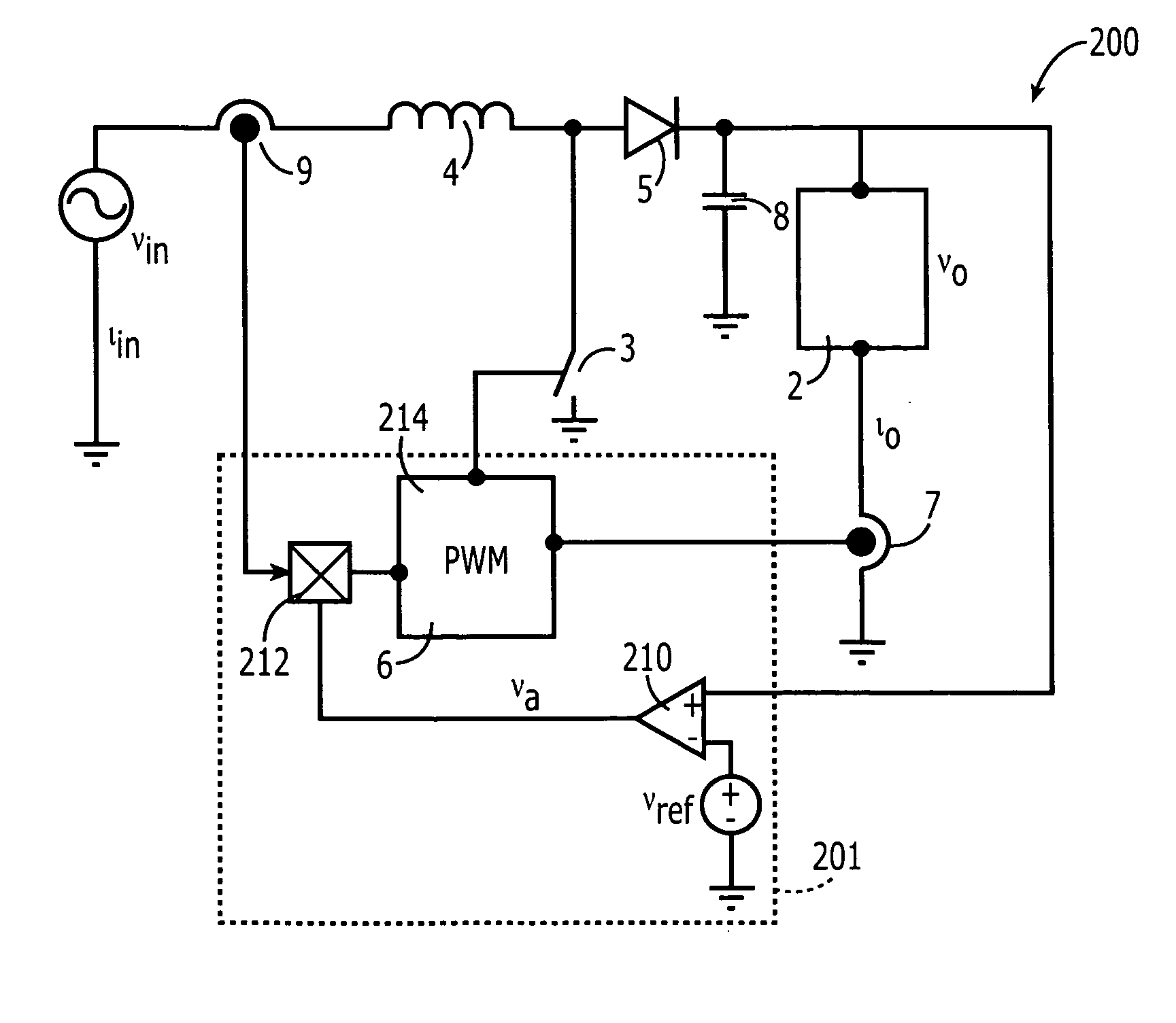
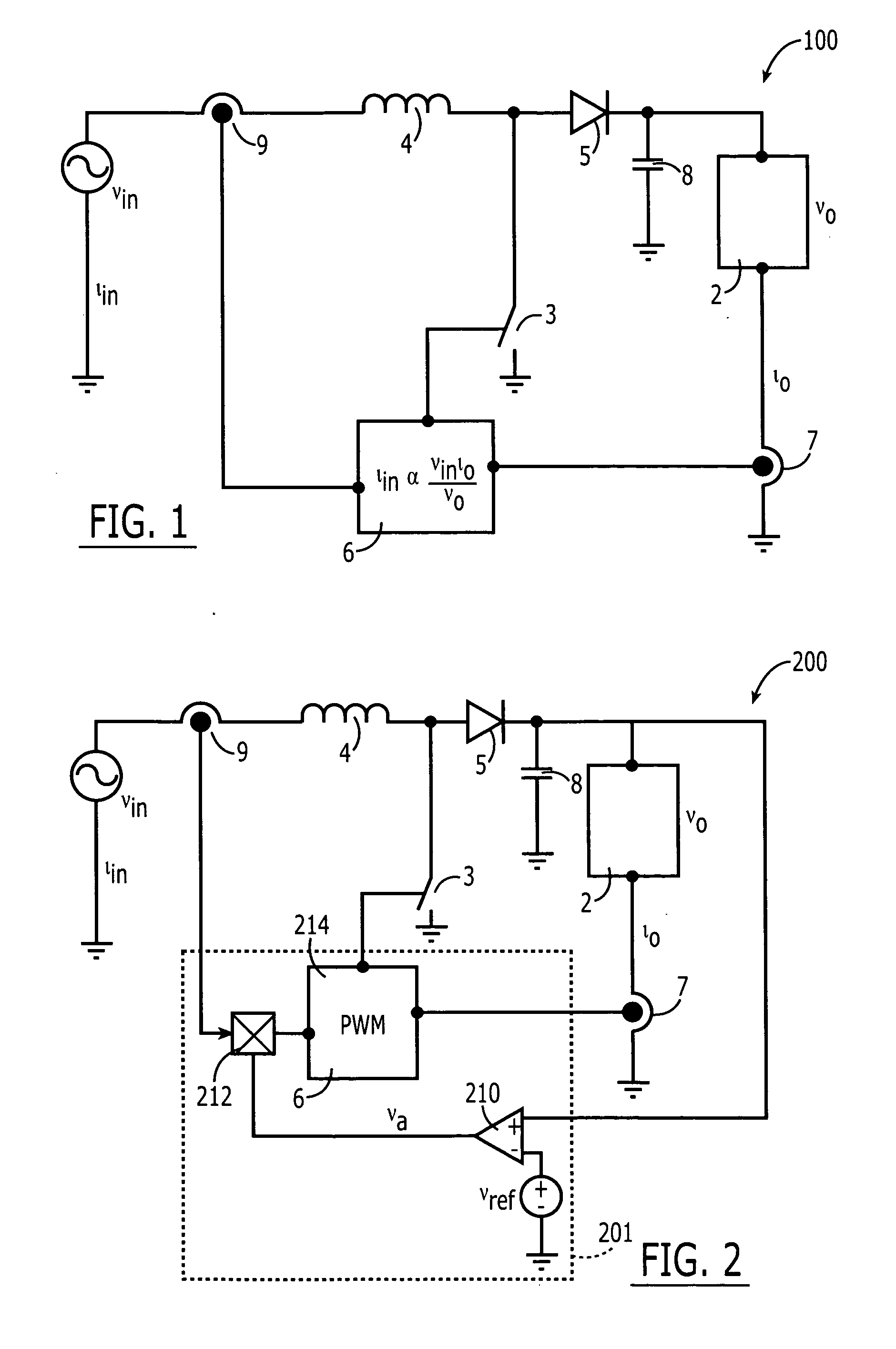
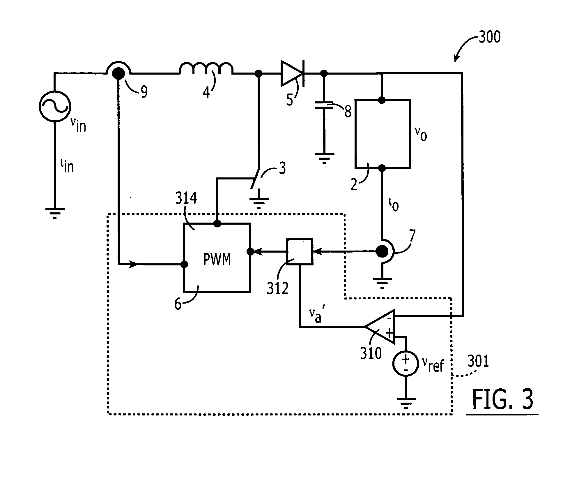
[0018] Specific exemplary embodiments of the invention now will be described with reference to the accompanying drawings. This invention may, however, be embodied in many different forms and should not be construed as limited to the embodiments set forth herein; rather, these embodiments are provided so that this disclosure will be thorough and complete, and will fully convey the scope of the invention to those skilled in the art. The terminology used in the detailed description of the particular exemplary embodiments illustrated in the accompanying drawings is not intended to be limiting of the invention. In the drawings, like numbers refer to like elements.

[0019] As used herein, the singular forms “a”, “an” and “the” are intended to include the plural forms as well, unless expressly stated otherwise. It will be further understood that the terms “includes,”“including” and / or “including,” when used in this specification, specify the presence of stated features, integers, steps, ope...


PUM


Abstract

A controller for a boost converter includes a first current sense input configured to receive an inductor current sense signal representative of a current in the inductor and a second current sense input configured to receive an output current sense signal representative of an output current of the boost converter. The controller further includes a control circuit configured to be coupled to a boost switch of the boost converter and to control the boost switch responsive to the received inductor current sense signal to force an input current of the boost converter directly proportional to the output current and to an input voltage of the boost converter and inversely proportional to an output voltage of the boost converter. The invention may be embodied as apparatus or methods.

Description

RELATED APPLICATIONS [0001] The present application is a continuation-in-part application of U.S. patent application Ser. No. 10 / 709,553 entitled “Method and Control Circuit for Power Factor Correction,” filed May 13, 2004, and claims the benefit of U.S. Provisional Application Ser. No. 60 / 594,933 entitled “Power Factor Correction Circuits for Wide Input Voltage Range,” filed May 20, 2005, and United States Provisional Application Ser. No. 60 / 595,635 entitled “Modulation Method for PFC Boost Converters,” filed Jul. 22, 2005, the disclosures of each of which are hereby incorporated by reference herein in their entireties.BACKGROUND OF THE INVENTION [0002] The present invention relates to power electronics apparatus and methods and, more particularly, to power converter apparatus and methods. [0003] Boost converters are used in a variety of applications. For example, in power supply applications, a boost converter may be used to generate a boosted DC voltage from an input AC or DC vol...

Claims


Application Information

Patent Timeline
IPC IPC(8): G05F1/70
CPCH02M3/156H02M2001/0022H02M2001/0019H02M1/0019H02M1/0022
Inventor COHEN, ISAAC
Owner LAMBDA AMERICAS
Why Eureka
Try Eureka