Angle detector with self-calibration capability

a detector and self-calibration technology, applied in the field ofangle detectors, can solve the problems of limiting the amount of size reduction possible, the coaxiality is generally not perfect, and the angle data obtained from the position of the scale line is error-prone, so as to achieve accurate measurement stably over a long period, and the effect of easy calibration work

Active Publication Date: 2006-03-02
NAT INST OF ADVANCED IND SCI & TECH
View PDF6 Cites 53 Cited by
  • Summary
  • Abstract
  • Description
  • Claims
  • Application Information

AI Technical Summary

Benefits of technology

[0015] This invention can provide an angle detector with self-calibration capability, whose self-calibration capability enables detection of scale line calibration values and error and the like owing to rotational shaft coupling, which enables ca

Problems solved by technology

Since the scale lines of an angle detector are created artificially, they are not exactly equiangular, so that errors occur in the angle data obtained from the positions of the sca

Method used


Image

  • Angle detector with self-calibration capability
  • Angle detector with self-calibration capability
  • Angle detector with self-calibration capability

Examples


second embodiment

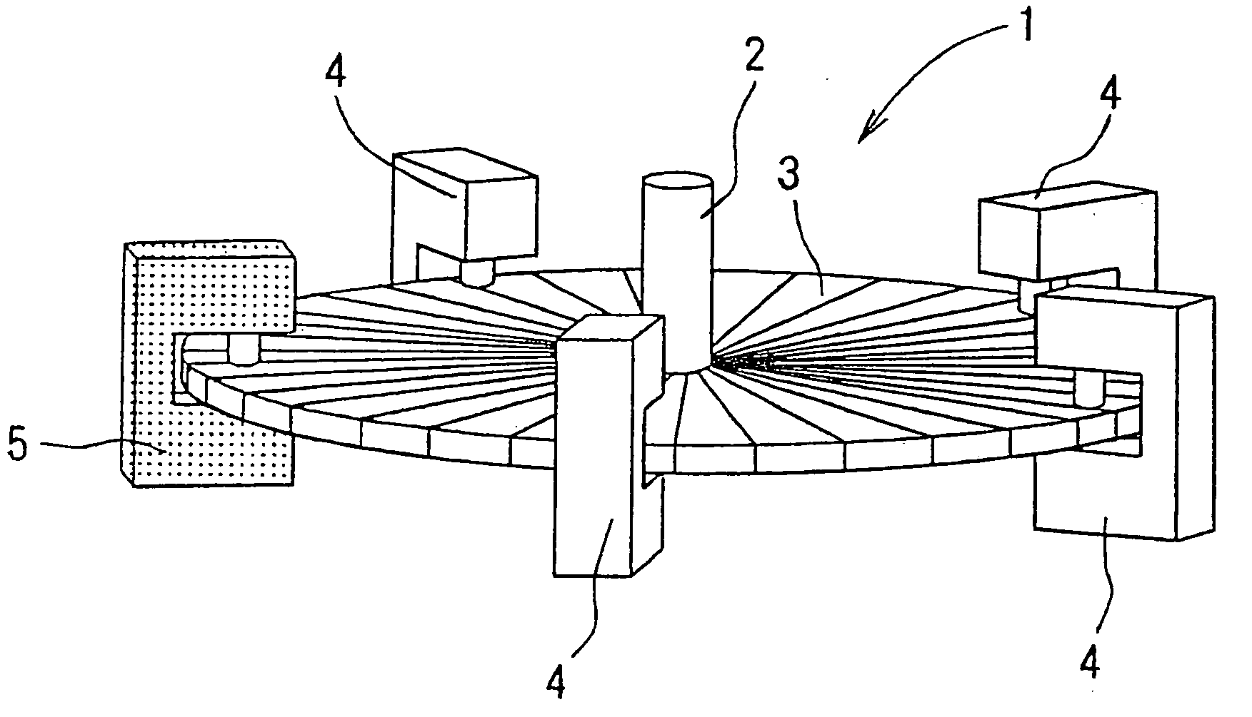
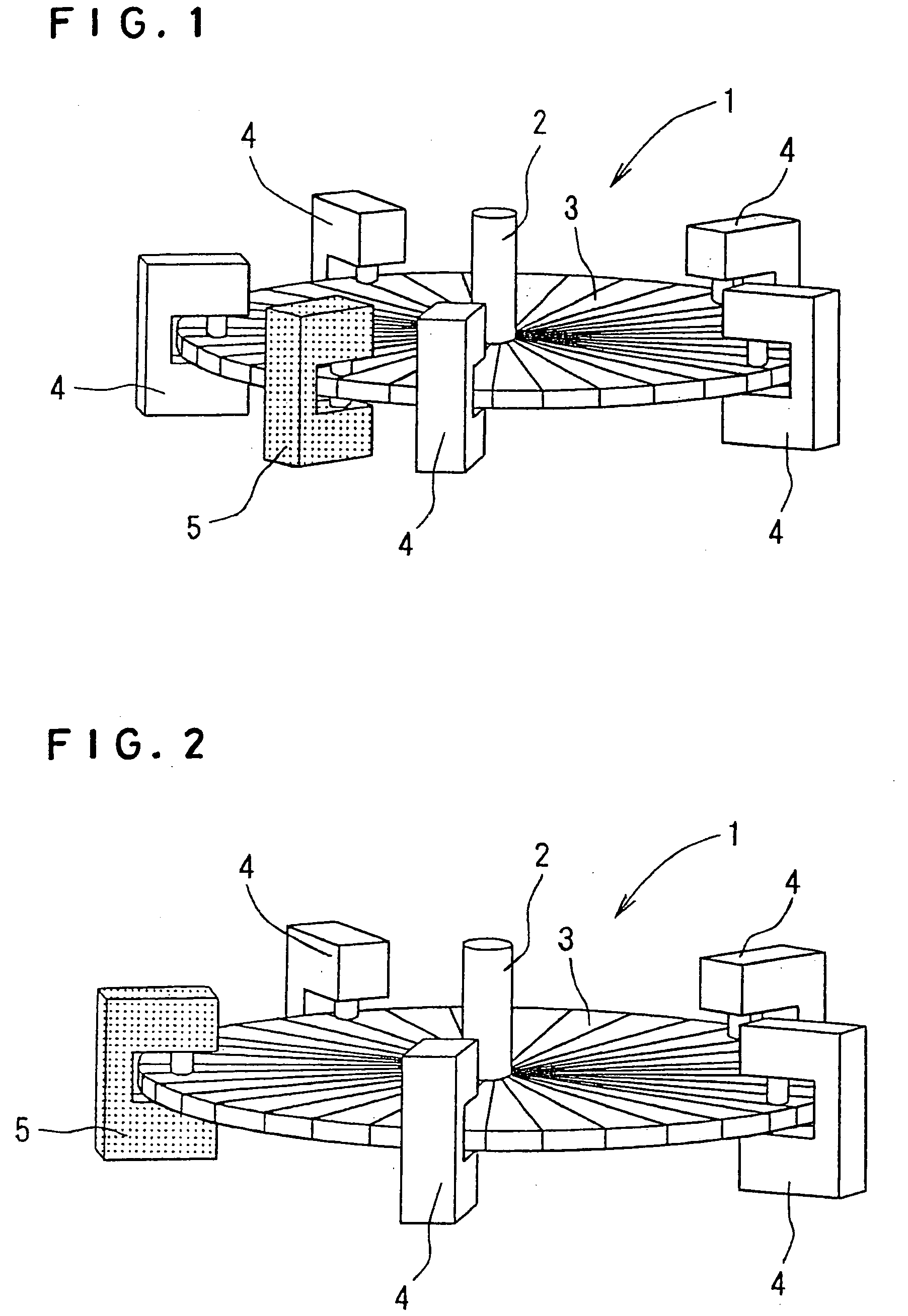
[0038] The degree to which the size of the angle detector shown in FIG. 1 can be reduced is limited because when the second scale read head 5 is installed among the first scale read heads 4, 4 . . . , inter-head interference is apt to arise if the size of the angle detector scale disk is made too small. Therefore, as shown in FIG. 2, in the second embodiment, one of the first scale read heads is made to assume the role of the second scale read head. In other words, the second scale read head 5 is installed at the location of one of the first scale read heads 4, 4 . . . spaced equidistantly around the periphery of the scale disk 3 to replace the same.

first embodiment

[0039] In this arrangement of the scale read heads, as in the first embodiment, where the first scale read heads are designated A1, A2, A3, . . . , ANH, and the second scale read head serving as a reference head is designated B1, the scale angle signals Bi and Ai,j detected by these heads can be expressed by the following equations.

Bi=bi

Ai,j=ai+(j−1)NG / NH [0040] NG: Total number of scales on a rotary encoder [0041] NH: Total number of heads [0042] j: Head number, j=1, 2, . . . , NH [0043] i: Scale number, i=1, 2, , NG

[0044] Since Bi=Ai,j when the first head is considered the reference head, the differences SAi,j1 between the angle signal output by the reference head B1 and the angle signals Ai, j and the average SAVj thereof can be expressed by the following equations.

Sai,j=Ai,1−Ai,j=ai−ai+(j−1)NG / ND

SAVi=⁢1ND⁢∑j=1ND⁢SAi,j=⁢ai-1ND⁢(ai+ai+NG⁢ / ⁢ND+ai+2⁢NG⁢ / ⁢ND+…+ai+(j-1)⁢NG⁢ / ⁢ND)

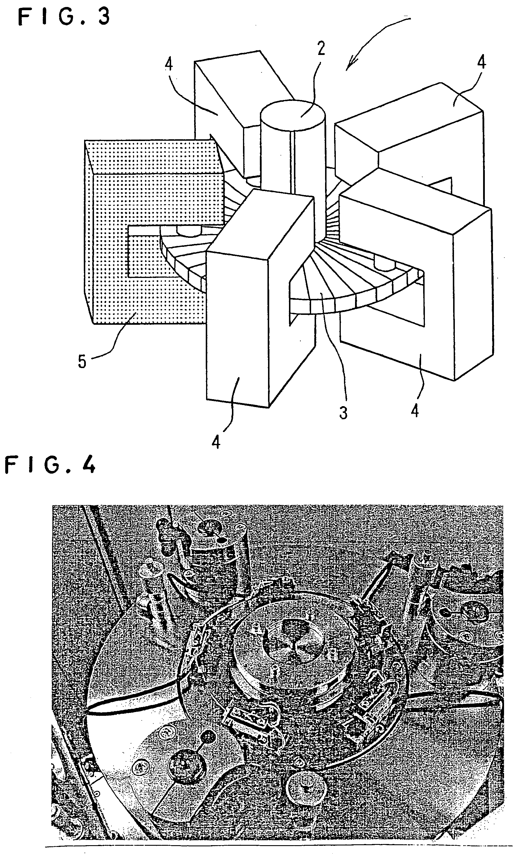
[0045] As exemplified in FIG. 3, this configuration minimizes the spacing required among the heads, ther...


PUM


Abstract

An angle detector with self-calibration capability has a number of first scale read heads and one second scale read head around the periphery of a single scale disk and includes means for performing self-calibration by determining measurement differences between the second scale read head and the individual first scale read heads and calculating the average thereof.

Description

BACKGROUND OF THE INVENTION [0001] 1. Field of the Invention [0002] This invention relates to an angle detector such as a rotary encoder for detecting rotation angle, particularly to an angle detector provided with self-calibration capability that enables calculation of calibration values for scale lines that include angle data error owing to attachment eccentricity in the use environment, angle detector aging, and the like. [0003] 2. Description of the Prior Art [0004] Rotary encoders and similar angle detectors operate on the general principle of using a read head to count scale lines formed at the periphery of a circular disk and output the counted value as angle data. Various devices are in use such as those shown in FIGS. 6 and 7. Since the scale lines of an angle detector are created artificially, they are not exactly equiangular, so that errors occur in the angle data obtained from the positions of the scale lines. The radial straight lines in FIG. 8 represent ideal scale lin...

Claims


Application Information

Patent Timeline
IPC IPC(8): G01R33/10
CPCG01D5/24452G01D5/3473G01D5/24485G01D18/001
Inventor WATANABE, TSUKASAMASUDA, TADASHI
Owner NAT INST OF ADVANCED IND SCI & TECH
Why Eureka
Try Eureka