
Digital camera

a digital camera and camera body technology, applied in the field of digital cameras, can solve the problems of not being able to obtain the image the photographer desires, unable to judge the appropriate exposure value of the object, and unable to take more than one photograph image having the same composition

Inactive Publication Date: 2006-03-02
PENTAX RICOH IMAGING CO LTD
View PDF6 Cites 67 Cited by
  • Summary
  • Abstract
  • Description
  • Claims
  • Application Information

AI Technical Summary

Benefits of technology

[0009] Therefore, an object of the present invention is to provide a digital camera, which can obtain bracket images based on a plurality of parameters for which several steps are set.

Problems solved by technology

Sometimes it is difficult to judge the appropriate exposure value when the object is photographed.
Further, when an object moves fast, it is impossible for more than one photograph image having the same composition to be taken because the opportunity for photographing it is very short.
However, if there are too many steps for setting only one parameter e.g. exposure value, it often happens that the image which the photographer desires is not obtained.
In this method, another parameter has to be set manually by operating an operation device, and this operation takes a long time.
Therefore, it is difficult for users to select the most desirable image from the plurality of photograph images.

Method used


Image

  • Digital camera
  • Digital camera
  • Digital camera

Examples


first embodiment

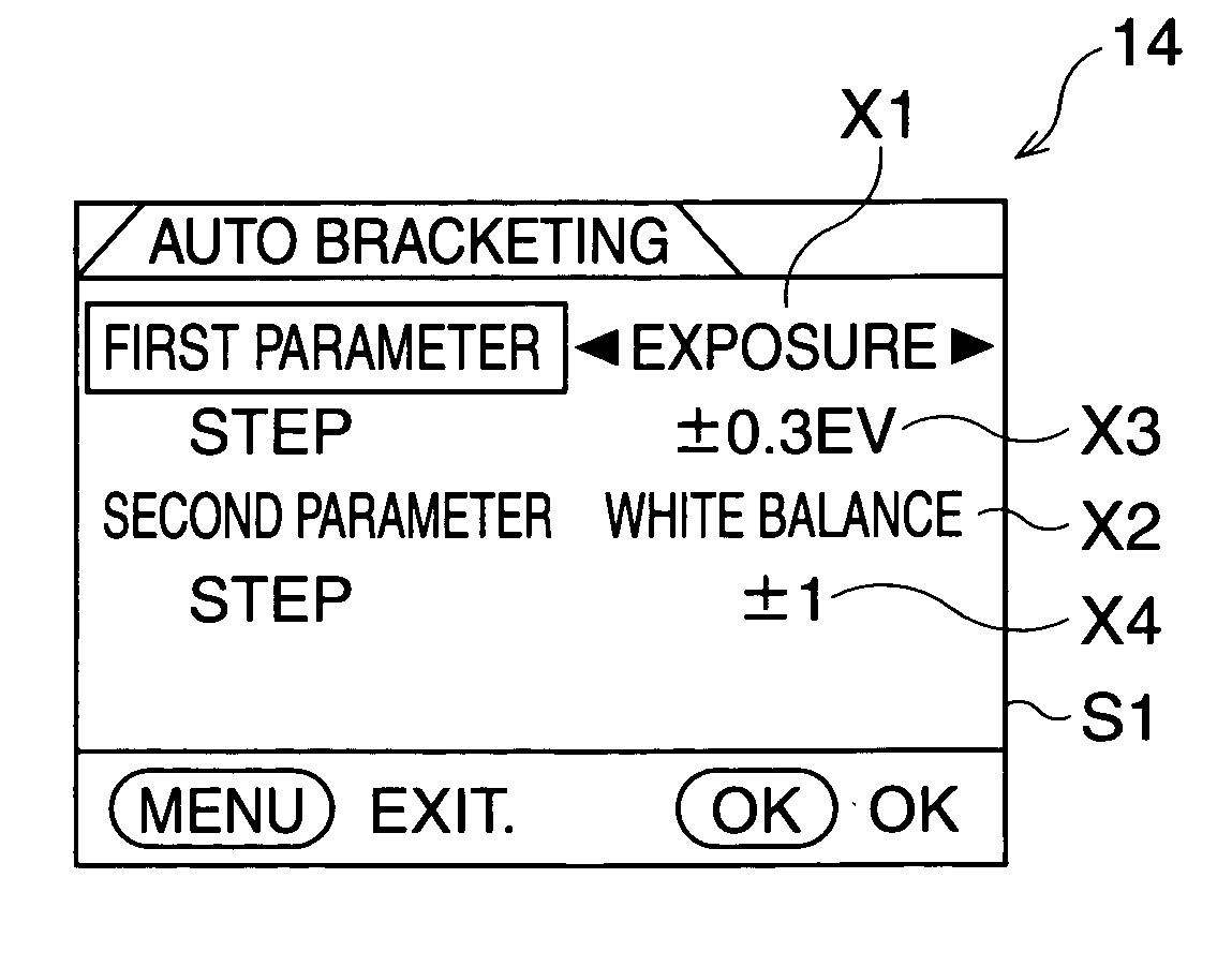
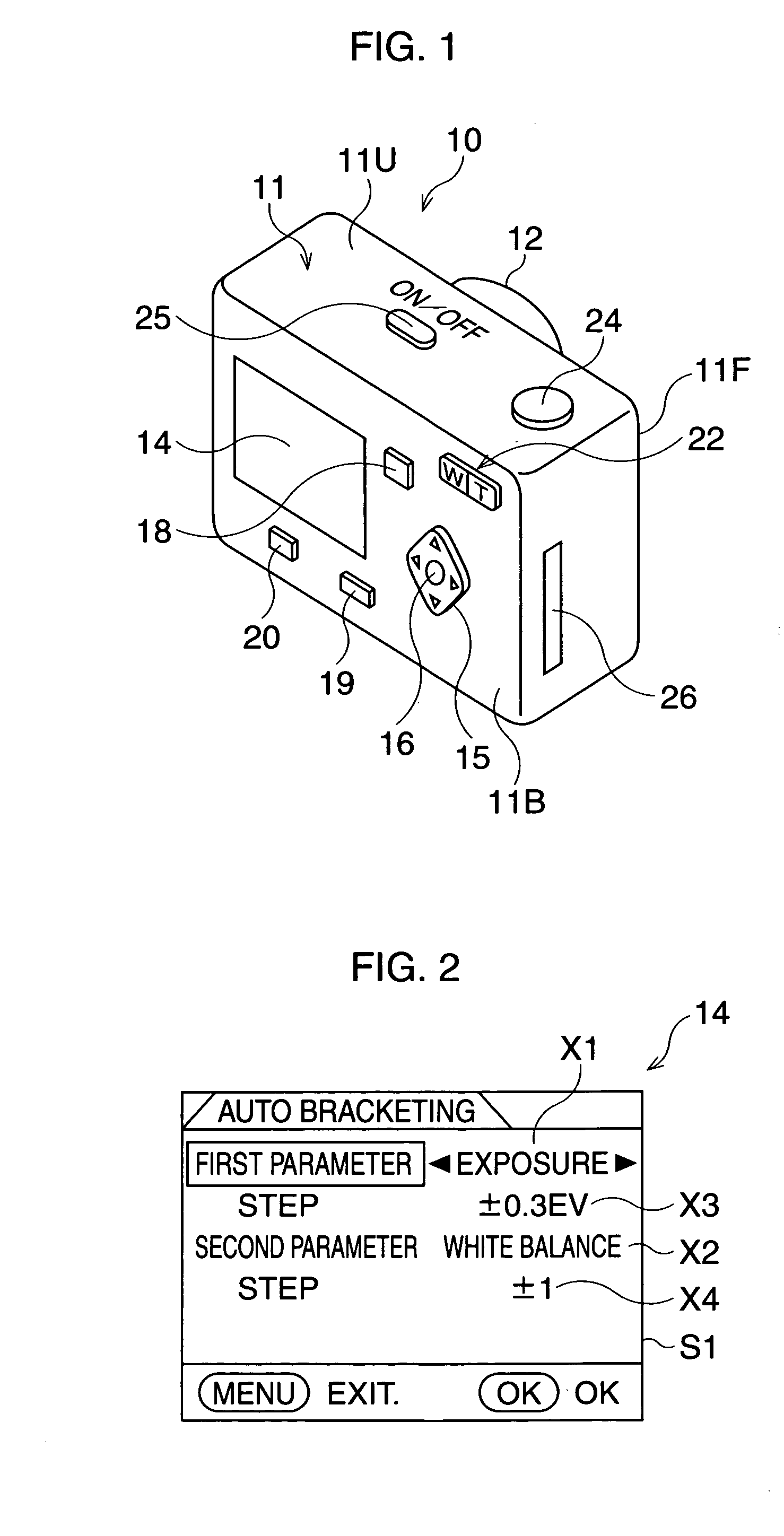
[0040]FIG. 1 shows a perspective view of a digital camera in a The digital camera 10 is provided with a camera body 11 having an upper surface 11U, a back surface 11B, and a front surface 11F. The camera body 11 is provided with a photograph lens system 12 at the center of the front surface 1F. The camera body 11 is provided with a LCD monitor 14 at the left side of the back surface 11B.

[0041] Reflected light from an object, which is received at the photograph lens system 12, is converted to image signals, and then the image signals are converted to photograph image, which are displayed on the LCD monitor 14 as a still picture image.

[0042] A 4-way controller switch 15 is provided at the right side of the LCD monitor 14, and an OK switch 16 is provided at the center of the 4-way controller switch 15. A replay switch 18, a menu switch 19, and a bracket switch 20 are provided on the back surface 11B around the LCD monitor 14, a zoom switch 22 is provided on the back surface 11B above...

second embodiment

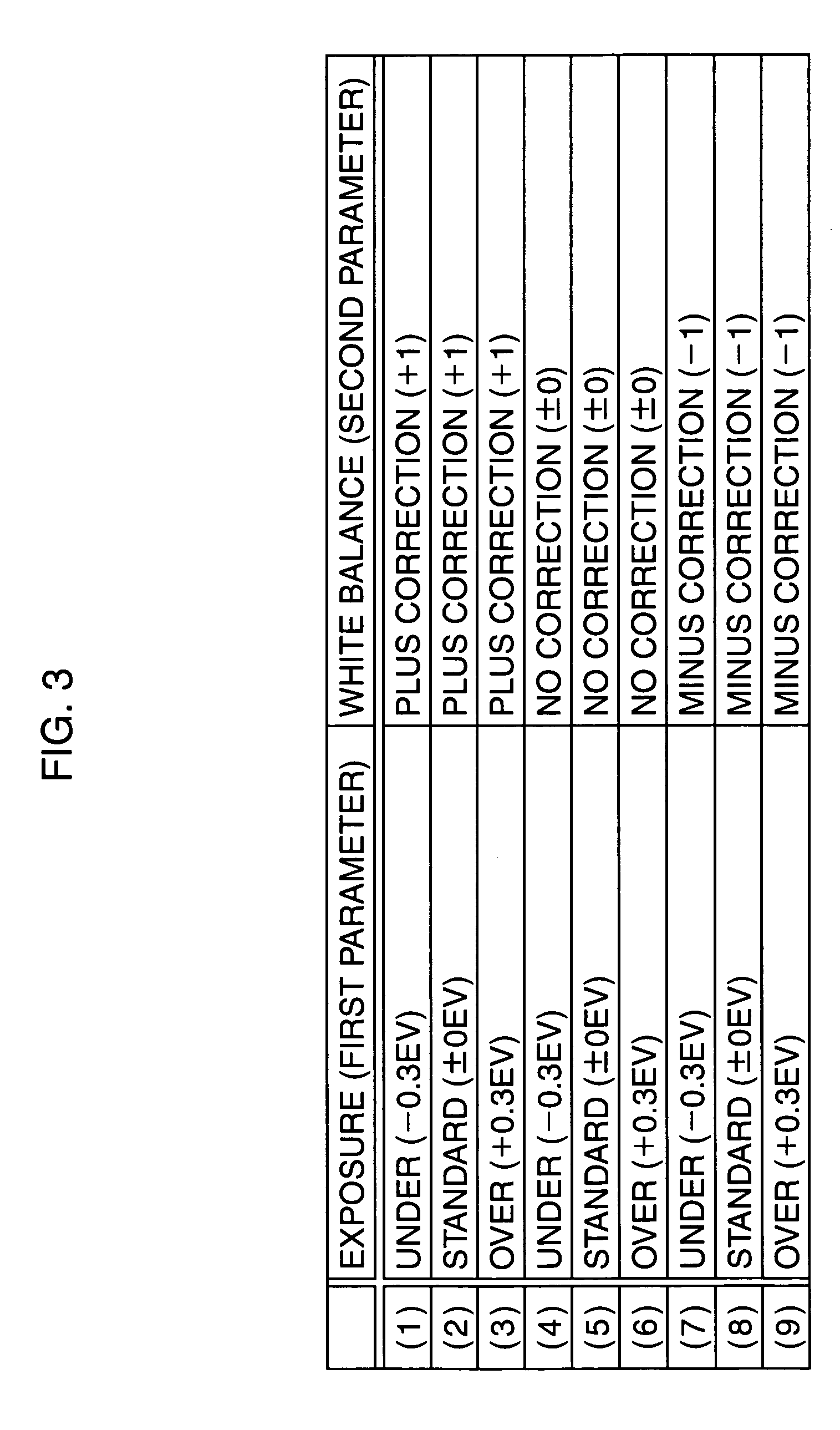
[0097] The FIG. 12 shows the routine for displaying the photograph image in the As described above, the twenty-seven photograph images are generated when the release button is pushed once in the bracket mode, and these twenty-seven photograph images are composed of one of the first, second, and third display images 81, 82, and 83.

[0098] In this routine, the second display image 82 is displayed at step S240 at first, and then the center unit display image (5) is surrounded by the selected frame 75 at step S241 as shown in FIG. 10. At step S242, whether the replay switch 18 is operated is determined. If it is determined that the switch 18 is operated, the display image which is displayed on the monitor 14 is changed at step S244. Namely, if the display image which is displayed on the monitor 14 is the first display image 81 the display image is changed to the second display image 82. Similarly, it is changed from the second or third image 82 or 83 to the third or first image 83 or 81...


PUM


Abstract

A digital camera generates a plurality of photograph image as a bracket image of an object. The digital camera comprises a setting processor that sets a plurality of steps for first and second parameters, a first bracket processor that obtains a plurality of intermediate images of the object based on each the step of the first parameter, and a second bracket processor that obtains a plurality of photograph images from each of the intermediate images based on each step of the second parameter.

Description

BACKGROUND OF THE INVENTION [0001] 1. Field of the Invention [0002] The present invention relates to a digital camera, more particularly, it relates to a digital camera capable of taking bracket images. [0003] 2. Description of the Related Art [0004] Conventionally, it is known that a digital camera takes bracket images while setting gradual steps for a parameter of photograph condition e.g. exposure value, as shown in Japanese Unexamined Patent Publication (KOKAI) NO. 2003-87608. In this case, when a release button is pushed, an object is photographed continuously so as to obtain a plurality of photograph images, of which the compositions are substantially same, but which are taken under different photograph conditions from one another. [0005] Sometimes it is difficult to judge the appropriate exposure value when the object is photographed. In this case, if the bracket images are taken, it is possible to choose the best image which is photographed under the appropriate exposure val...

Claims


Application Information

Patent Timeline
IPC IPC(8): H04N5/222
CPCH04N5/232H04N5/2356H04N5/23293H04N23/743
Inventor OKAMOTO, TEPPEITATAMIYA, HISASHI
Owner PENTAX RICOH IMAGING CO LTD
Learn More