Liquid crystal display

a liquid crystal display and liquid crystal technology, applied in non-linear optics, instruments, optics, etc., can solve the problems of display failure, liquid crystal b>1006/b> increasing with the size of the panel, and the cell gap becomes undetectedly large in the lower part of the panel, etc., to achieve the effect of degrading the display quality

Inactive Publication Date: 2006-03-02
SHARP KK
View PDF2 Cites 24 Cited by
  • Summary
  • Abstract
  • Description
  • Claims
  • Application Information

AI Technical Summary

Benefits of technology

[0016] According to the invention, the linear convex portion (rib) is formed in the panel in a direction that is orthogonal to the direction in which gravity acts on the panel when the panel is vertically erected. The rib is formed such that a gap of 2 μm or less is left between the rib and the opposite substrate. As a result, when the liquid crystal moves through the gap, a resistance acts against the movement, and the possibility of an irregularity attributable to gravity therefore becomes smaller than that in common liquid crystal displays. The possibility of an irregularity attributable to gravity can be small even when pillar spacers are formed with a small height with respect to the total amount of liquid crystal dispensed where the ODF method is employed. It is therefore possible to provide a great manufactural margin to accommodate some variation of the height of the pillar spacers. The rib does not result in any irregularity of the cell thickness because it does not contact the opposite substrate normally and have no influence on the disposition density of the pillar spacers. The invention makes it possible to provide a liquid crystal display in which degradation of display quality due to an irregularity attributable to gravity is suppressed.

Problems solved by technology

On the contrary, when the height of the pillar spacers 1003 is too small, the liquid crystal 1006 moves downward due to the weight of itself when the panel is vertically erected, in which case an irregularity attributable to gravity occurs in that the cell gap becomes undesirably great in a lower part of the panel.
In either case, a display failure can occur.
However, the mass of the liquid crystal 1006 increases with the size of the panel, and the margin allowed for irregularities attributable to gravity becomes small accordingly.
Under the circumstance, it is becoming difficult to accommodate a great margin for a process using the ODF method.

Method used


Image

  • Liquid crystal display
  • Liquid crystal display
  • Liquid crystal display

Examples


first embodiment

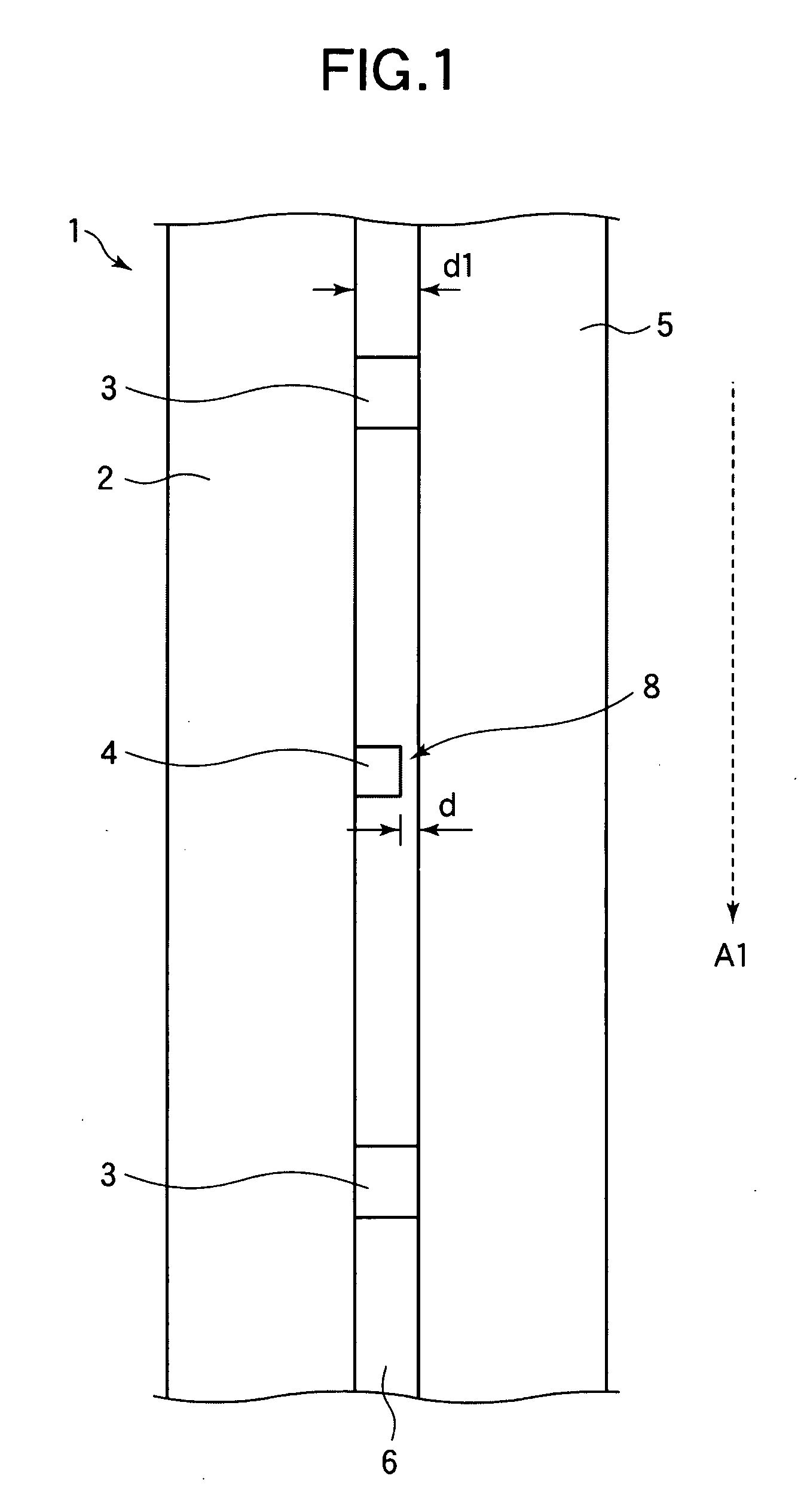
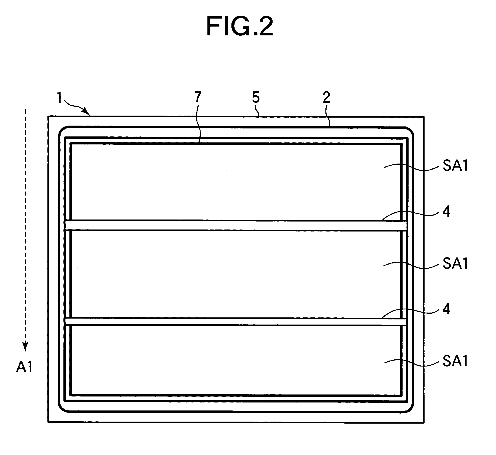
[0047] A liquid crystal display according to a first embodiment of the invention will now be described with reference to FIGS. 1 and 2. FIG. 1 shows a partial section of a panel of a liquid crystal display 1 according to the present embodiment in an upright position of the display in which panel surfaces are in parallel with a vertical direction A1. FIG. 2 is a view of the liquid crystal display 1 of the present embodiment taken in a direction toward the panel surfaces in the upright position of the display in which the panel surfaces are in parallel with the vertical direction A1. As shown in FIG. 1, the liquid crystal display 1 includes an opposite substrate 2 and an array substrate 5 disposed opposite to each other and a liquid crystal 6 sealed between the opposite substrate 2 and the array substrate 5. An opposite electrode and color filters (both of which are not shown) are formed on the opposite substrate 2. Gate bus lines, drain bus lines, TFT elements, pixel electrodes, stor...

second embodiment

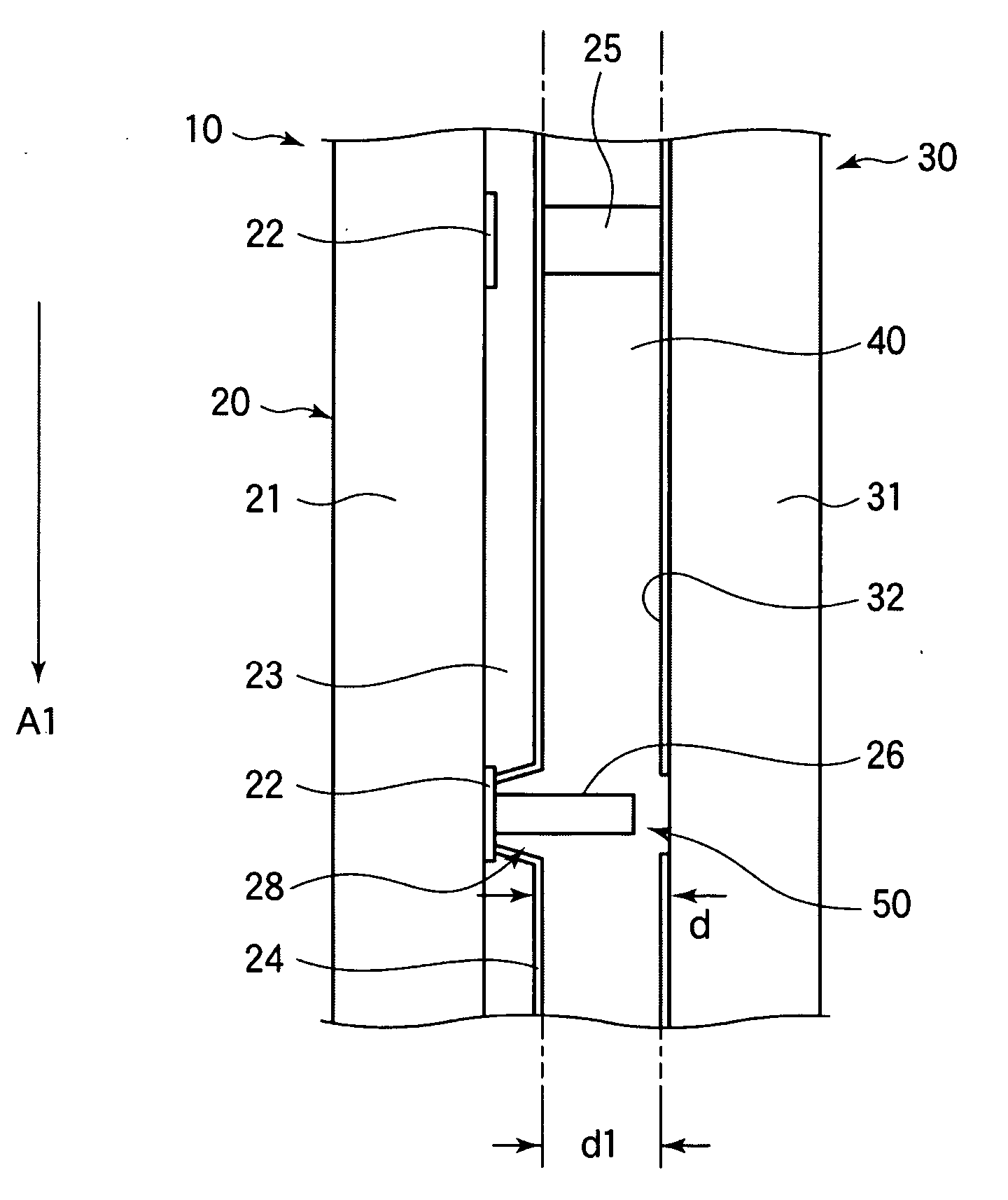
[0051] A liquid crystal display according to a second embodiment of the invention will now be described with reference to FIGS. 3 to 10. FIG. 3 shows a partial section of a panel of a liquid crystal display 1 according to the present embodiment in an upright position of the display in which panel surfaces are in parallel with a vertical direction A1. FIG. 4 is a view of the liquid crystal display 1 of the present embodiment taken in a direction toward the panel surfaces in the upright position of the display in which the panel surfaces are in parallel with the vertical direction A1. While the first embodiment has shown an example in which ribs 4 are formed on a surface of an opposite substrate 2 of a liquid crystal display 1, the present embodiment is characterized in that recesses 28 are provided on an opposite substrate 20 and in that ribs 26 are formed on the bottoms of the recesses 28.

[0052] A black matrix (BM; shielding film) 22 for defining pixel regions is formed of such as ...

third embodiment

[0088] A third embodiment of the invention will now be described with reference to FIGS. 12 to 17. FIG. 12 is a plan view of a liquid crystal display according to the present embodiment. While the first and the second embodiments have shown examples in which ribs 4 and 26 are formed on opposite substrates 2 of liquid crystal displays 1, respectively, the present embodiment will show an example in which ribs 90 are formed on an array substrate 81.

[0089]FIG. 12 shows a configuration of nine pixels on an array substrate 81 of a liquid crystal display. Specifically, as shown in FIG. 12, the array substrate 81 of the liquid crystal display has a plurality of gate bus lines 82 extending in the horizontal direction in FIG. 12 and a plurality of drain bus lines 83 extending in the vertical direction in FIG. 12 across the gate bus lines 82 with an insulation film interposed therebetween, the bus lines being provided on a transparent substrate.

[0090] TFT elements 84 are formed in the vicini...


PUM

PropertyMeasurementUnit
widthaaaaaaaaaa
atmospheric pressureaaaaaaaaaa
pressureaaaaaaaaaa

Abstract

The invention relates to a liquid crystal display filled with a liquid crystal by dispensing the liquid crystal onto a substrate, combining the substrate with an opposite substrate in vacuum with the surface of the substrate having the liquid crystal thereon facing the opposite substrate, and restoring the atmospheric pressure. The invention provides a liquid crystal display in which degradation of display quality due to an irregularity attributable to gravity can be suppressed. The liquid crystal display has a pair of substrates opposite to each other, a liquid crystal sealed between the substrates, a convex portion protruding into the liquid crystal from a surface of at least either of the pair of substrates and extending in a substantially horizontal direction when the pair of substrates is erected in the vertical direction, and a gap formed between the protruding end of the convex portion and a surface of the other substrate.

Description

BACKGROUND OF THE INVENTION [0001] 1. Field of the Invention [0002] The present invention relates to a liquid crystal display that is filled with a liquid crystal by dispensing the liquid crystal on a substrate, combining the substrate with an opposite substrate in vacuum with the surface having the liquid crystal dispensed thereon facing the opposite substrate, and thereafter restoring the atmospheric pressure. [0003] 2. Description of the Related Art [0004] There is increasing demand for liquid crystal displays, and display panels are being manufactured for various purposes, including small panels having a screen size on the order of a few inches and large panels having a screen size on the order of several tens inches to be used for televisions. Active matrix type color liquid crystal displays utilizing thin film transistors (TFTs) as switching elements are attracting attention as the main stream of flat panel displays, and there is strong demand for further improvements in the d...

Claims


Application Information

Patent Timeline
Patent Type & Authority Applications(United States)
IPC IPC(8): G02F1/1337
CPCG02F1/1341G02F1/13394G02F1/133377
Inventor TAKAGI, TAKASHI
Owner SHARP KK
Why Eureka
Try Eureka