Display module

a display module and backlight technology, applied in the field of backlight modules, can solve the problems of insufficient color saturation, insufficient white light led development techniques, and inferior performance of small lcd modules using leds as light source generators, and achieve the effect of improving color saturation

Inactive Publication Date: 2006-03-02
INNOLUX CORP +1
View PDF2 Cites 19 Cited by
  • Summary
  • Abstract
  • Description
  • Claims
  • Application Information

AI Technical Summary

Benefits of technology

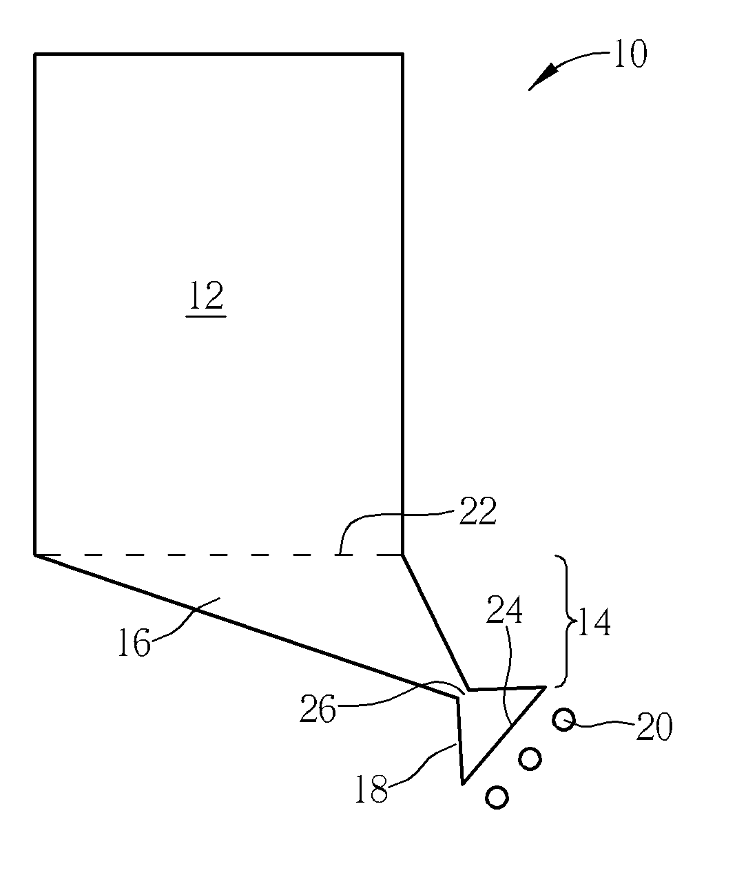
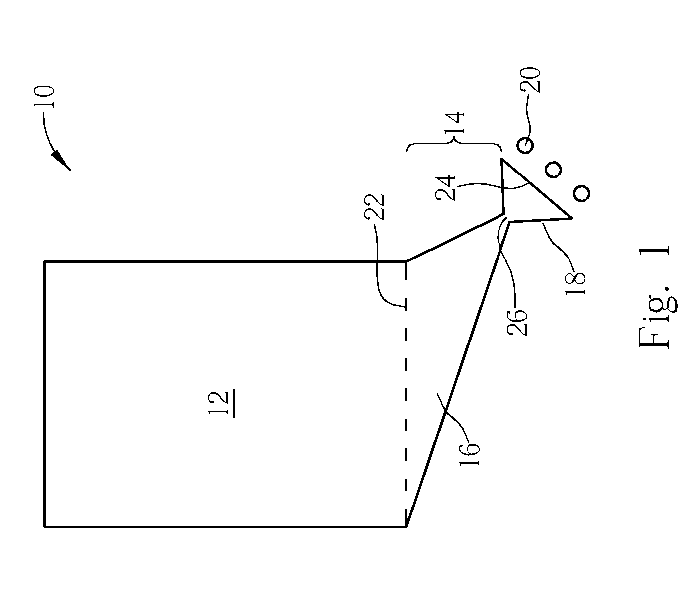
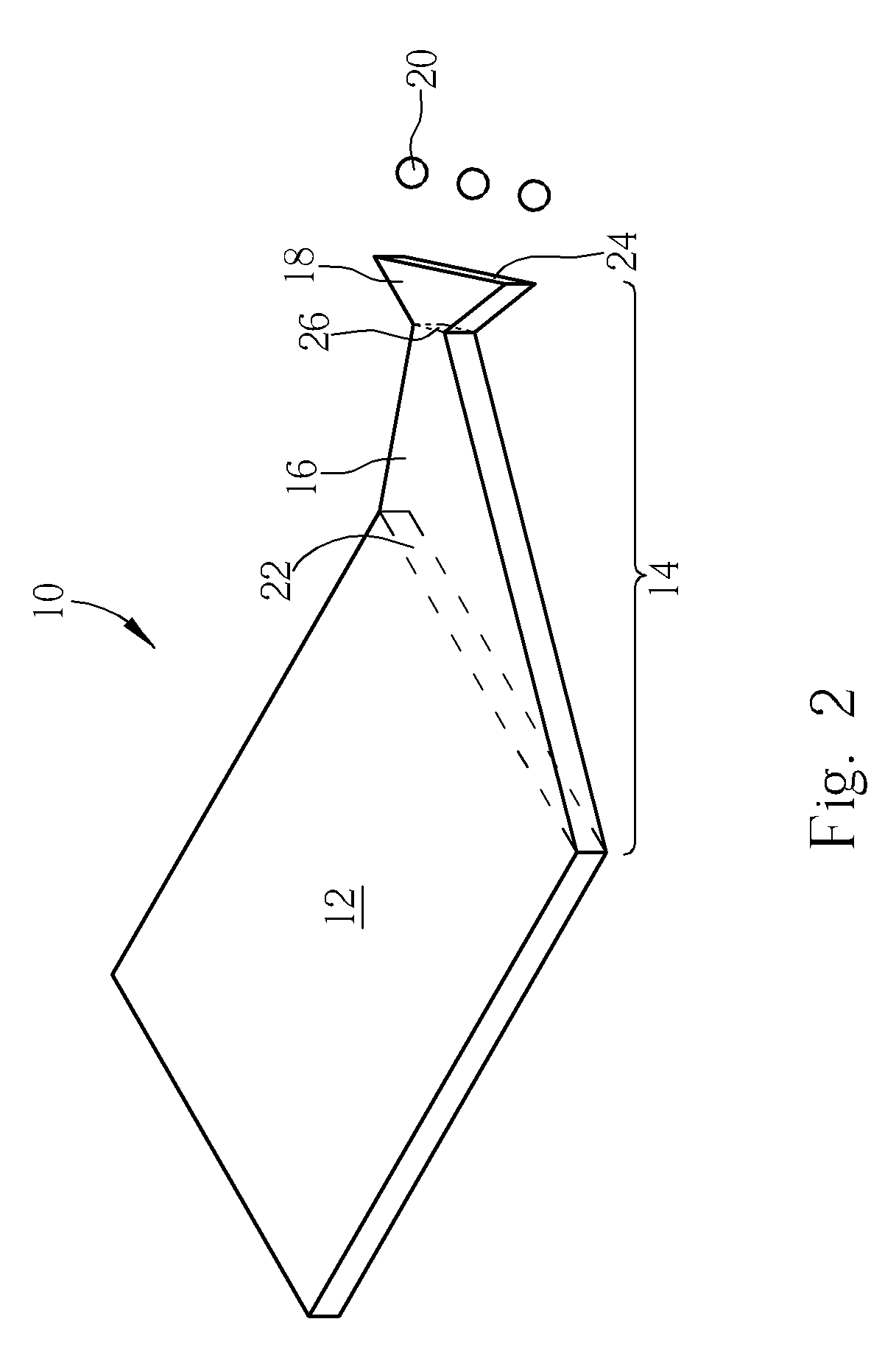
[0009] Since the light guide plate of the present invention has a unique light-mixing structure, the backlight module need only utilize conventional multicolor LEDs such as red, blue, and green ones as the light source generator. This allows the light guide plate to produce white light via the light-mixing structure to meet the demand of the light source generator required by the LCD panel for providing better color saturation.

Problems solved by technology

However, the technique of developing white light LEDs is not mature, so that a conventional LED light source generator uses fluorescent powders with a monochromatic LED (such as a blue LED) to obtain white light.
However, a drawback of this method is insufficient color saturation of the LCD module due to a smaller distribution of the color range so that the performance of a small LCD module using an LED as its light source generator is inferior to that of the large LCD monitor having conventional fluorescent lamps.

Method used


Image

  • Display module
  • Display module
  • Display module

Examples


second embodiment

[0023] Please refer to FIG. 4. FIG. 4 is a top view of a backlight module 50 according to the present invention. The backlight module 50 includes a light guide plate 52 and a multicolor light source generator 54. The multicolor light source generator 54 includes a plurality of LEDs of different colors. The multicolor light source generator 54 shown in FIG. 4 has a blue LED 54a, a green LED 54b, and a red LED 54c.

[0024] The light guide plate 52 includes a transparent plate 56 and a light-mixing structure 58. The light-mixing structure 58 includes a light-dispersing body 60 and a light-convergence body 62, wherein the light-dispersing body 60 is connected to two sides of the transparent plate 56, and the contact planes are the light-exit plane of the light-dispersing body 60 and the light incident plane of the transparent plate 56 as well. In order to provide a better path for conducting light into the transparent plate 56, the area of the light-exit plane of the light-dispersing bod...

third embodiment

[0028] Please refer to FIG. 6. FIG. 6 is a top view of a backlight module according to the present invention. For convenience, each element shown in FIG. 6 adopts the reference numerals of FIG. 4. As shown in FIG. 6, the light-convergence body 62 includes two light-incidence planes 68a and 68b, intersecting to form an obtuse angle A where the multicolor light source generator 54 is positioned nearby. In addition, the surface of the light-incidence planes 68a and 68b includes V-shaped notches.

fourth embodiment

[0029] Please refer to FIG. 7, which is a top view of a backlight module according to the present invention. In the present embodiment, the light-convergence body 62 further includes a light-dispersing mechanism 74, positioned in the light-convergence body 62 and which is in the shape of a triangular plate. The light-dispersing mechanism 74 is a hollow triangular plate, that is, a hollow triangular plate is situated inside the light-convergence body 62, wherein a side of the hollow triangular plate is approximately parallel to the light-incidence plane 68 to allow blue, green, and red light produced by the blue LED 54a, the green LED 54b, and the red LED 54c respectively to enter the light-incidence plane 68 and then mix well via the light-dispersing mechanism 74.


PUM


Abstract

A backlight module has a light guide plate having a transparent plate and a light-mixing structure. The light-mixing structure contains a light-convergence body and a light-dispersing body connected with each other to form an hourglass-shaped structure. With the light-mixing structure, the light guide plate can mix light beams of different colors to produce white light beams.

Description

BACKGROUND OF INVENTION [0001] 1. Field of the Invention [0002] The present invention is related to a backlight module, and more particularly, to a backlight module able to provide a liquid crystal display with a light source generator having a high color rendering property. [0003] 2. Description of the Prior Art [0004] Backlight modules are one of the major component devices of liquid crystal display (LCD) products, and have been widely applied to digital cameras, mobile phones, personal digital assistants (PDAs), computer monitors, and flat TVs at present. Generally, a backlight module, being mostly installed in the backside of a display panel, includes a light source generator, a light guide plate, and several sorts of light diffusion elements. The light guide plate is one of the light diffusion elements used for diffusing light generated from the light source generator to the display panel for providing homogeneous brightness to the display panel. [0005] Generally, backlight mod...

Claims


Application Information

Patent Timeline
Patent Type & Authority Applications(United States)
IPC IPC(8): F21V7/04
CPCG02B6/0016G02B6/0068G02B6/0041G02B6/0018
Inventor YU, CHUAN-PEI
Owner INNOLUX CORP
Why Eureka
Try Eureka