Method and apparatus for frequency correcting a periodic signal

a frequency correction and periodic signal technology, applied in the field of electric time reference circuits, can solve the problems of increasing the area of the circuit board, degrading the reliability of the device incorporating, and adding costs

Inactive Publication Date: 2006-03-02
MOTOROLA MOBILITY LLC
View PDF8 Cites 31 Cited by
  • Summary
  • Abstract
  • Description
  • Claims
  • Application Information

AI Technical Summary

Problems solved by technology

The use of a 32.768 kHz crystal oscillator, however, adds cost, increases circuit board area, and can degrade the reliability of the device incorporating it.
These crystals represent a significant cost component for the device.
The crystal element can also incur cracking (and thus failure) when exposed to a drop or severe vibration environment.

Method used


Image

  • Method and apparatus for frequency correcting a periodic signal
  • Method and apparatus for frequency correcting a periodic signal
  • Method and apparatus for frequency correcting a periodic signal

Examples


Embodiment Construction

[0014] As required, detailed embodiments of the present invention are disclosed herein; however, it is to be understood that the disclosed embodiments are merely exemplary of the invention, which can be embodied in various forms as described in the non-limiting exemplary embodiments of FIGS. 1 through 6. Therefore, specific structural and functional details disclosed herein are not to be interpreted as limiting, but merely as a basis for the claims and as a representative basis for teaching one skilled in the art to variously employ the present invention in virtually any appropriately detailed structure. Further, the terms and phrases used herein are not intended to be limiting; but rather, to provide an understandable description of the invention.

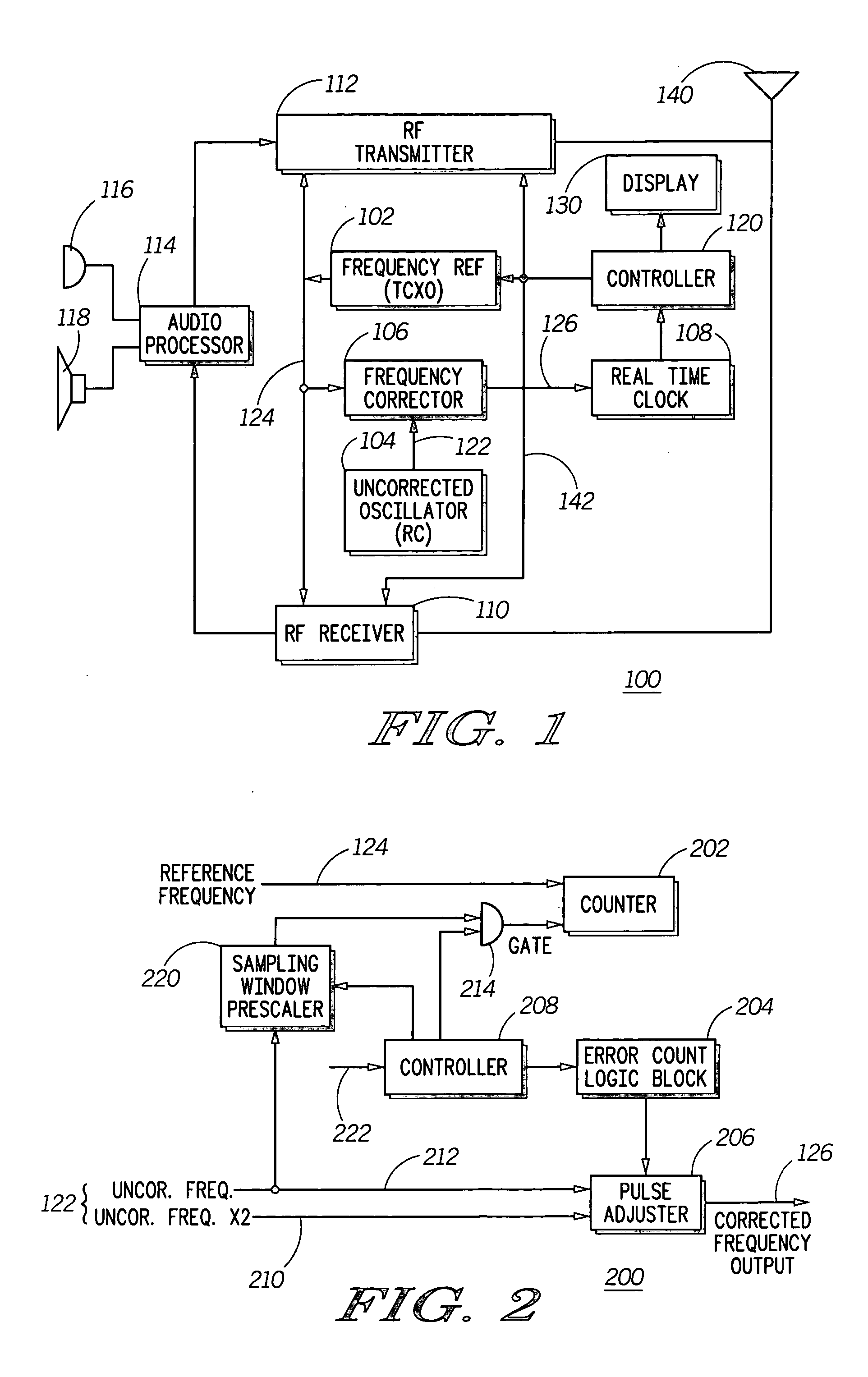
[0015]FIG. 1 illustrates a block diagram of a cellular telephone 100 incorporating an exemplary embodiment of the present invention. The exemplary cellular telephone 100 operates with advanced mobile wireless communications systems and is...


PUM


Abstract

A method and apparatus to correct a periodic signal, such as a frequency reference, based upon another frequency reference. A lower accuracy frequency signal generator (104) provides an uncorrected frequency reference signal (122) to a frequency corrector (106). Frequency corrector (106) counts cycles of a frequency reference signal (124), as generated by a higher accuracy reference generator (102) for a time period derived from the uncorrected frequency signal. Based upon the cycles counted, pulses are added or removed from the uncorrected frequency signal (122) to produce a corrected frequency signal (126). A ratio of pulses to be removed from the uncorrected frequency signal (122) is determined from the number of cycles counted and a counter arrangement is provided to automatically remove the required ratio of pulses from the uncorrected frequency signal (122).

Description

FIELD OF THE INVENTION [0001] The present invention generally relates to the field of electrical time reference circuits and more particularly to electrical frequency reference generating circuits that correct periodic signals based upon a frequency standard. BACKGROUND OF THE INVENTION [0002] Many electronic devices, such as cellular phones and PDAs, require a low frequency oscillator circuit that is commonly used to run a Real Time Clock (RTC) logic block and also to drive other circuits during low power modes. Many devices use a 32.768 kHz crystal oscillator for this purpose. Such devices typically include a higher frequency, more accurate reference oscillator that is disabled during these low power modes. While a precise (e.g., + / −50 ppm) frequency reference is generally not needed while operating in a low power mode, precise frequency references are needed for RTC functions, such as alarms or appointment reminders. This has resulted in requiring the RTC clock, and therefore the...

Claims


Application Information

Patent Timeline
Patent Type & Authority Applications(United States)
IPC IPC(8): H04L27/06
CPCG04G3/00H03L7/08G04G3/022
Inventor BALLANTYNE, WAYNE WIGGINSHATHAWAY, ROGER C.NOGUEIRA, SILVIO LUIZ LIMAMINASI, DAVID HARTLEYMIRANDA-KNAPP, CARLOS ANTONIOWENINGER, DARREN V.
Owner MOTOROLA MOBILITY LLC
Why Eureka
Try Eureka