
Speaker enclosure with a liquid chamber for mounting a speaker driver

Inactive Publication Date: 2006-03-02
JAKUBAITIS FR J
View PDF3 Cites 14 Cited by
  • Summary
  • Abstract
  • Description
  • Claims
  • Application Information

AI Technical Summary

Benefits of technology

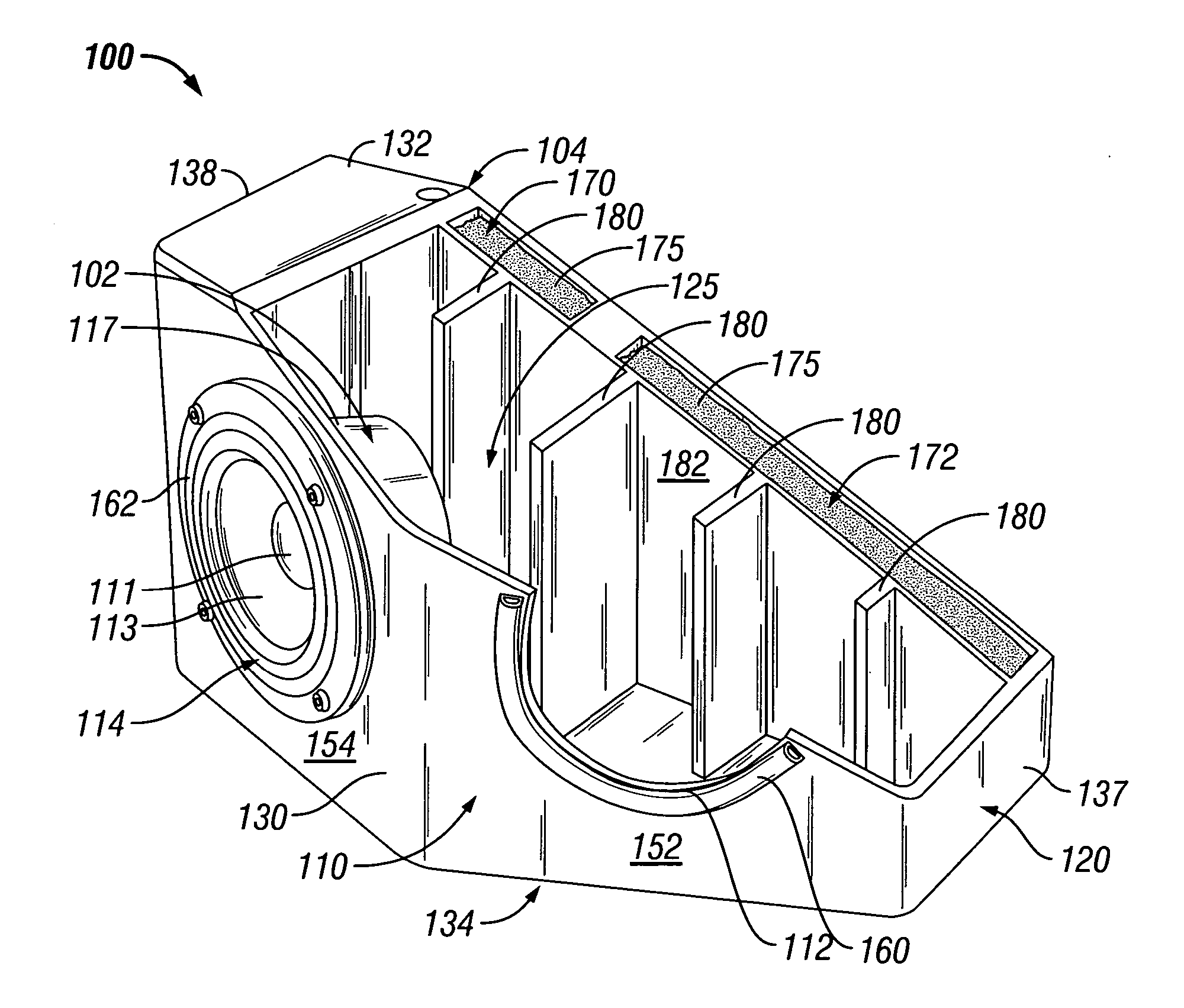
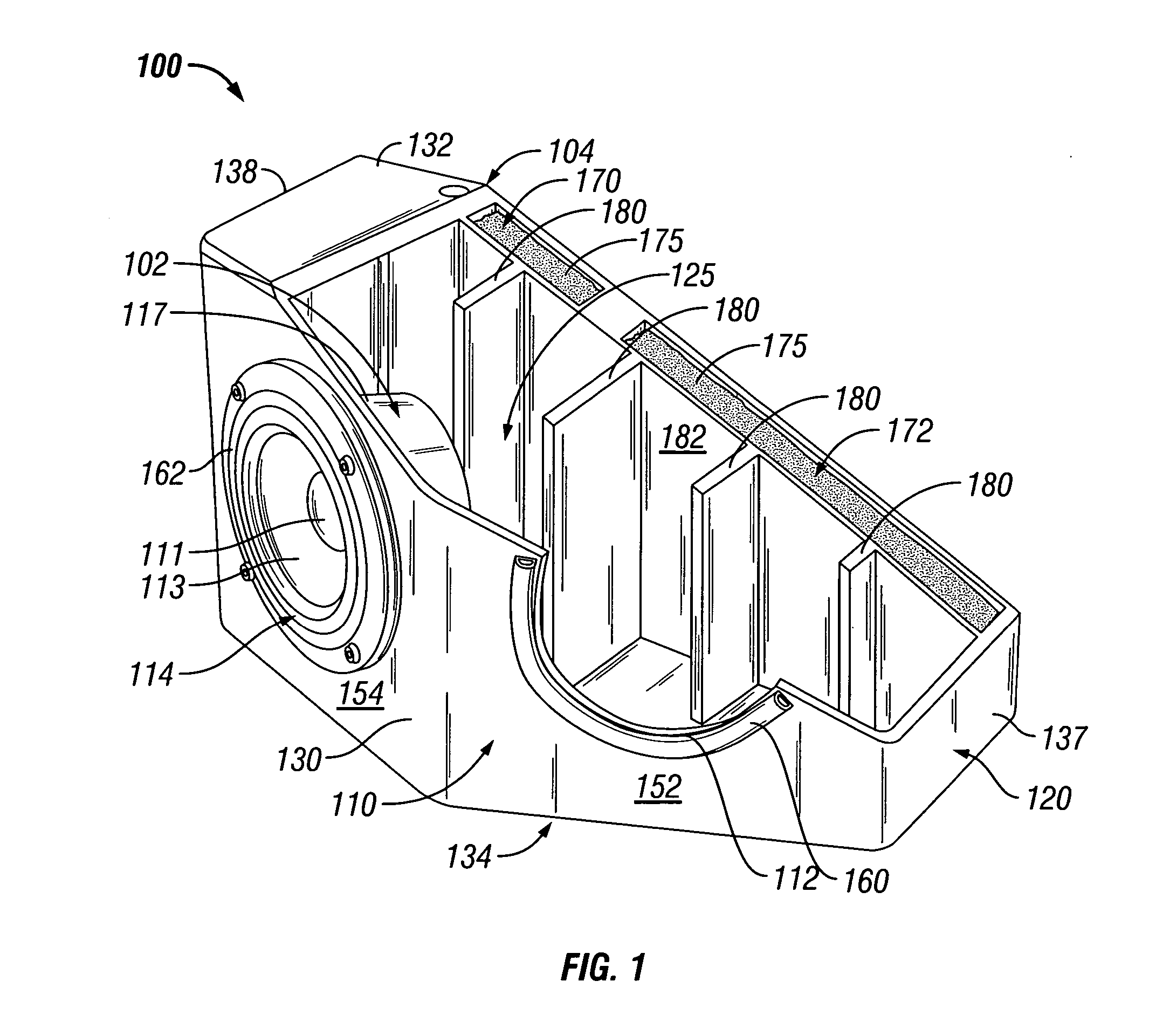
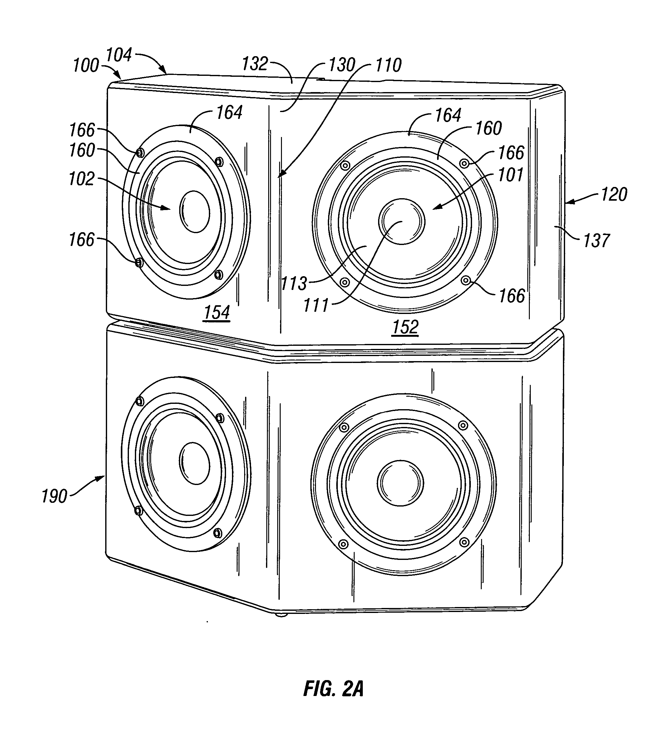
[0011] In one aspect, the invention may be regarded as a speaker enclosure to mount and enclose a speaker driver, in which the speaker enclosure includes a front mounting portion and a body portion. The front mounting portion has an opening to mount the speaker driver. The body portion extends rearwardly from the mounting portion and the speaker driver is enclosed by the front mounting portion and the body portion within an interior of the speaker enclosure. Particularly, the body portion includes a liquid chamber. The liquid chamber may be filled with a liquid to affect the tuning of the speaker enclosure and to enhance lower frequencies.
[0014] By utilizing a speaker enclosure having a liquid chamber that includes a pre-determined amount of liquid, in conjunction with one or more baffles within the interior of the speaker enclosure, the overall speaker can be optimally tuned such that the natural harmonics of the speaker drivers are preserved and lower frequencies or bass sounds are amplified. This results in a small speaker having high-fidelity characteristics, including great bass sound, commonly associated with large speakers.

Problems solved by technology

However, many potential speaker customers reside in living areas with a limited amount of space that can be dedicated for the use and placement of speakers.
Nonetheless, even with the box stuffing inserted in the small speaker enclosure, small speakers still generally sound “boxy”.
Further, by putting box stuffing within the speaker enclosure, although some of the boxy sound may be eliminated, the box stuffing unfortunately negatively affects the natural harmonics of the speaker driver thereby resulting in a lower quality sound emanating from the speaker.
Also, in small speakers, a hole or port is typically made within the speaker enclosure in order to attempt to increase the amount of low frequency or bass sound that emanates from the speaker, which is already limited due to the small size of the speaker enclosure.
Unfortunately, even with these adjustments, today's small speakers are inadequate to satisfy the high-fidelity tastes of many potential speaker customers.
Particularly, the combination of the “boxy sound,” the degradation of the natural harmonics of the speaker driver by the box stuffing, and the inadequate low frequency bass sound results in most potential speaker customers being dissatisfied with small speakers.

Method used


Image

  • Speaker enclosure with a liquid chamber for mounting a speaker driver
  • Speaker enclosure with a liquid chamber for mounting a speaker driver
  • Speaker enclosure with a liquid chamber for mounting a speaker driver

Examples


Embodiment Construction

[0019] In the following description, the various embodiments of the present invention will be described in detail. However, such details are included to facilitate understanding of the invention and to describe exemplary embodiments for implementing the invention. Such details should not be used to limit the invention to the particular embodiments described because other variations and embodiments are possible while staying within the scope of the invention. Furthermore, although numerous details are set forth in order to provide a thorough understanding of the present invention, it will be apparent to one skilled in the art that these specific details are not required in order to practice the present invention. In other instances details such as, well-known methods, components, processes, interfaces, electrical structures, circuits, etc. are not described in detail, or are shown in block diagram form, in order not to obscure the present invention.

[0020] With reference to FIG. 1, w...


PUM


Abstract

Disclosed is a speaker including a speaker enclosure having a liquid chamber to mount and enclose a speaker driver. The speaker enclosure includes a front mounting portion and a body portion. The front mounting portion has an opening to mount the speaker driver and the body portion extends rearwardly from the mounting portion and the speaker driver is enclosed by the front mounting portion and the body portion within an interior of the speaker enclosure. Particularly, the body portion includes a liquid chamber that may be filled with a liquid to affect the tuning of the speaker enclosure to enhance lower frequencies.

Description

BACKGROUND [0001] 1. Field of the Invention [0002] This invention relates to speaker enclosures. In particular, the invention relates to a speaker enclosure with a liquid chamber for mounting a speaker driver. [0003] 2. Description of Related Art [0004] A speaker driver is an electric acoustic transducer that converts alternating electric currents into sound waves with the same frequency characteristics and wave-forms that are within the range of human hearing (approximately 16 Hz to 20 KHz). In particular, a speaker driver typically includes a coil of wire, called a voice coil, which is held in the field of a magnet. When alternating currents flow in the coil, a changing magnetic field is produced around the coil. This field interacts with the field from the magnet to produce reciprocal forces on the coil. The coil is mounted so that it can move as these forces occur. The coil is typically physically attached to a cone shaped diaphragm, which vibrates along with the coil. The movin...

Claims


Application Information

Patent Timeline
IPC IPC(8): H04R25/00
CPCH04R1/2811
Inventor JAKUBAITIS, FRANK J.
Owner JAKUBAITIS FR J
Learn More