Adaptive power amplifier and radio frequency transmitter thereof

a power amplifier and radio frequency transmitter technology, applied in the direction of amplifier modification to reduce non-linear distortion, high frequency amplifiers, transmission, etc., can solve the problems of increased hardware structure, excessive current consumption, and the inability of the integrated system to reflect the change in output level, etc., to achieve high efficiency and linear characteristics

Active Publication Date: 2017-10-12
DIALOG SEMICON KOREA INC
View PDF6 Cites 10 Cited by
  • Summary
  • Abstract
  • Description
  • Claims
  • Application Information

AI Technical Summary

Benefits of technology

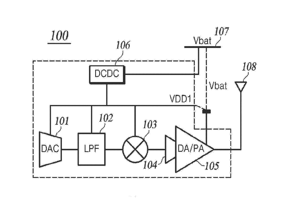
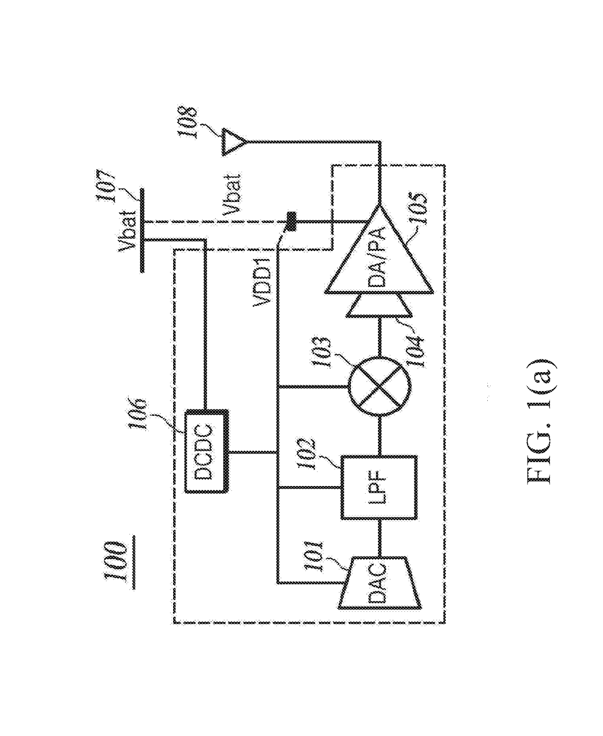
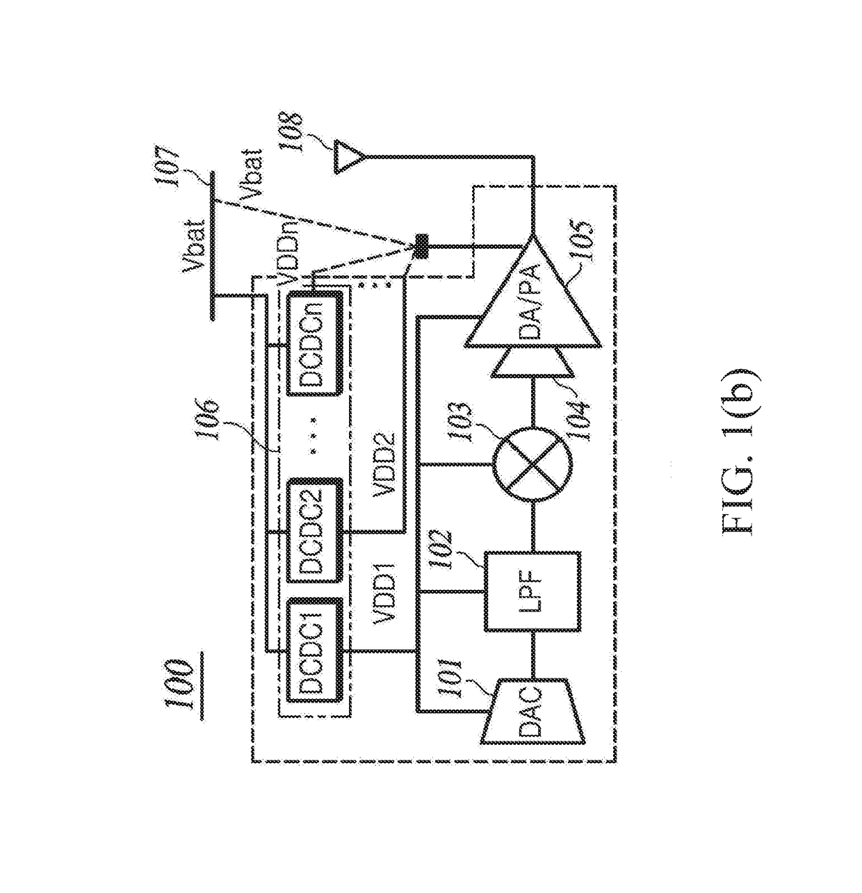
[0023]In view of the aforementioned descriptions, one embodiment of the present invention has the following effects. A radio frequency transmitter corresponds a plurality of supply voltages and selectively applies the supply voltages so that the transmitter release the maximum output power based on the supply voltages.
[0024]Furthermore, the input matching circuit and the output matching circuit changes resistances based on the different supply voltages so that the power amplifier operates based on corresponding supply voltage in a high efficiency and linear characteristic.

Problems solved by technology

In addition, if the power amplifier is integrated to the transmitter, the integrated system can not reflect changed output level.
When the output power of the transmitter is insufficient, it is required to use additional power amplifier in the external portion.
On the contrary, if the output power of the transmitter is larger, it may cause excessive current consumption.
In this manner, since a function of the integrated chip must include a controllable supply switch, thus, the hardware structure is more complex and the linearization of the transmitted signal is degraded.
In particular, because of the increased size of the entire chip area due to excessive concentration, thus, the cost is increased.

Method used


Image

  • Adaptive power amplifier and radio frequency transmitter thereof
  • Adaptive power amplifier and radio frequency transmitter thereof
  • Adaptive power amplifier and radio frequency transmitter thereof

Examples


Embodiment Construction

[0030]The following embodiments with reference to the accompanying drawings and the detail of a partial embodiment of the present invention will be described. It is noted that the constituent elements shown in the figures marked with reference symbols can be as closely as possible to the same constituent elements denoted by common symbols even though the constituent elements are shown in different figures. In addition, while describing the present invention, if the determination is a well known specific description form or function and may make the subject matter of the present invention obscure, detailed descriptions thereof are omitted.

[0031]In addition, when the constituent elements of the present invention will be described, the terms of first, second, A, B, (a), (b), etc. are used. Such terms are only used to distinguish one component from other components, and do not limit the nature, an order or sequence of the respective constituent elements. throughout the specification, wh...


PUM


Abstract

An adaptive power amplifier and a radio frequency transmitter thereof are described. The radio frequency transmitter is a transmitter to transmit a transmission signal for a wireless communication system. The radio frequency transmitter includes at least one direct-current (DC) to direct-current (DC) converter coupled to an external power supply device for operation, a digital-to-analog converter configured to convert a digital signal into an analog signal, a filter configured to filter a harmonic component of the analog signal to generate an input signal, a RF up-converter configured to up-convert the input signal according to a desired channel frequency for generating a modulated signal, and a power amplifying circuit coupled to the DC-to-DC converter and the external power supply device, for selectively receiving one of different supply voltages for operation, and amplifying the modulated signal to generate a RF output signal.

Description

BACKGROUND OF THE INVENTIONField of Invention[0001]The present invention relates to a technical field of an adaptive power amplifier and a radio frequency transmitter, and more particularly relates to an adaptive power amplifier and a radio frequency transmitter thereof corresponding to a plurality of different supply voltages.Description of Prior Art[0002]Some content described in this section simply provides the background of the present invention, and is not deemed as a prior art.[0003]The transceiver used in a wireless communication device, such as a cellular phone (e.g., cellular handset) or wireless network (e.g., WIFI protocol) includes the advantages of a low-power, low-cost, a miniaturized feature, a high output rate, and the like. In order to realize miniaturization in a transceiver with a low cost, a complementary-metal-oxide semiconductor (CMOS) manufacturing process is adopted, and the external components are embedded within the main radio frequency chip. Recently, in o...

Claims


Application Information

Patent Timeline
Patent Type & Authority Applications(United States)
IPC IPC(8): H03F1/32H03F1/22H04B1/04H03F3/45H03F3/24H03F3/193H03F1/02H03F1/56
CPCH03F1/3241H03F1/0227H03F1/223H03F1/56H03F3/45179H03F3/245H04B2001/0425H04B1/04H03F2200/222H03F2200/387H03F2200/165H03F2200/333H03F2200/451H03F3/193H03F1/0211H03F3/19H04B2001/0408H03F2203/45394H03F1/22H03F1/30H04B1/0458
Inventor KANG, MIN-CHULHWANG, MYUNG-WOON
Owner DIALOG SEMICON KOREA INC
Why Eureka
Try Eureka