H-bridge pulse generator

a pulse generator and hbridge technology, applied in the direction of mechanical vibration separation, process and machine control, instruments, etc., can solve the problems of circuit drawbacks without freewheeling diodes, further limitations in performance of shown circuits, etc., to achieve wide frequency response, increase efficiency, and increase output power

Inactive Publication Date: 2009-04-23
SMITH STEPHEN
View PDF6 Cites 21 Cited by
  • Summary
  • Abstract
  • Description
  • Claims
  • Application Information

AI Technical Summary

Benefits of technology

[0006]This invention is an electronic circuit that produces greater output power, increased efficiency, a wider frequency response and reduces ring-down noise in a physically smaller package compared to RF] pulse sources for EMATS. The invention is an electronic circuit without the need of an output transformer that produces greater output power, increased efficiency, a wider frequency response and reduces ring-down noise in a physically smaller package compared to conventional RF pulsers for EMATS. Specifically the H-bridge circuit topology provides several advantages for the EMAT pulse source. This circuit can produce transmitter pulses that are normally impeded by the transformer that is required with the push pull design. The output impedance of the design will be low with the upper two switches closed or the lower two switches closed.
[0010]It is another object of this invention to provide an EMAT pulse source that has increased efficiency over past sources, and
[0012]Still further, it is an object of this invention to provide a pulse source which reduces the ring-down noise in an EMAT system, and
[0015]Another object of this invention is to provide a pulse source for an EMAT which eliminates parasitic components in an EMAT which cause phase delay and undesirable ringing, and
[0016]A major object of this invention is to produce a pulse source which substantially increases the range of frequencies which can be used to drive an EMAT, and

Problems solved by technology

The drawback of this design is that for the same DC voltages applied in the half bridge the resulting AC voltage across the Load is one half that of a full bridge.
The performance of the shown circuit is that it is further limited by the turn off time (storage time and fall time) of the IGBT (insulated gate bipolar transistor).
The circuit has another drawback without a freewheeling diode to protect the switching device (IGBT).

Method used


Image

  • H-bridge pulse generator
  • H-bridge pulse generator
  • H-bridge pulse generator

Examples


Embodiment Construction

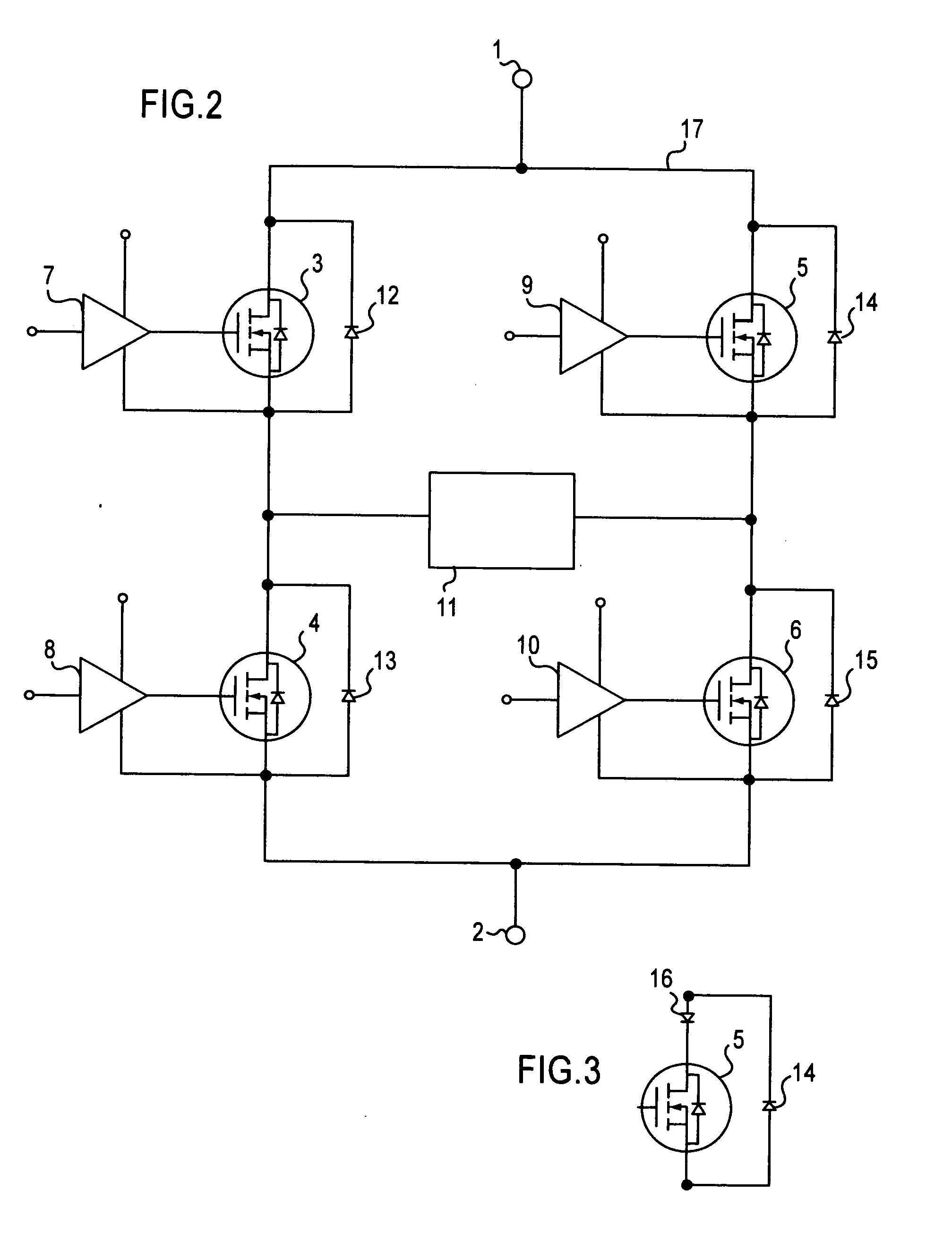
[0029]FIG. 1 shows a push pull topology typically used in an EMAT. This circuit provides a tone burst of current consisting of a specified number of cycles in an EMAT transmitter coil. The operation is for switch Q1 to be turned on for period of time and then switched off for a period of time, followed by the switching on for Q2 for the same period of time to avoid saturation of the transformer and then the Q2 is switched off at the end of the cycle. This operation produces a square wave output which can be transformed to the voltage required to drive the EMAT and its timing components. The use of the transformer however limits the range of frequencies for which sufficient drive current can be produced. Parasitic components such as stray capacitance and leakage inductance associated with the transformer can also consume power and limit the current that would otherwise be delivered to the EMAT. If the transformer is pulsed in a pattern other than a symmetric tone burst, it can limit ...


PUM


Abstract

A new type of circuit for driving an electromagnetic acoustic transducer (EMAT) which does not employ push-pull technology using a transformer but instant uses a novel circuit employing a series of Mosfet switches to correct all the disadvantages of using a transformer.

Description

BACKGROUND OF THE FIELD[0001]In the past EMATS (electromagnetic acoustic transducers) have typically used a push-pull topology. This type of circuit provides a tone burst of current consisting of a specified number of cycles in the EMAT transmitter coil. The system would be switched on for a period of time and then switched off for a period of time, followed by the switching on for the same period of time another coil to avoid saturation of the transformer and then switching it off at the end of the cycle. This cycle produces a square wave output that can be transformed into the voltage required to drive the EMAT and its tuning components.[0002]The historical problem with this system is that it substantially limits the range of frequencies for which sufficient drive current can be produced. Parasitic components such as stray capacitance and leakage inductance associated with the transformer can also consume power and limit the current that would otherwise be delivered to the EMAT. F...

Claims


Application Information

Patent Timeline
Patent Type & Authority Applications(United States)
IPC IPC(8): G05F1/10
CPCB06B1/0269
Inventor SMITH, STEPHEN
Owner SMITH STEPHEN
Why Eureka
Try Eureka