Exhaust emission control system for internal combustion engine

a technology of emission control system and internal combustion engine, which is applied in the direction of electrical control, machine/engine, electric control of exhaust treatment, etc., can solve the problems of unburned hc, increased pressure loss in the particulate filter, and increased engine efficiency, so as to prevent the engine from reducing the output power

Inactive Publication Date: 2007-01-18
DENSO CORP
View PDF27 Cites 22 Cited by
  • Summary
  • Abstract
  • Description
  • Claims
  • Application Information

AI Technical Summary

Benefits of technology

[0010] The present invention is achieved in view of the above-described issues, and has an object to provide an exhaust emission control system for an internal combustion engine that can prevent malfunctions caused by the particulate matters accumulated in a front end portion of a particulate filter, specifically to provide the system that can prevent an output power decrease of the engine due to a pressure loss increase in the particulate filter, a breakage of the particulate filter due to an excessive temperature increase in regenerating the particulate filter, etc.

Problems solved by technology

If the particulate matters collected in the particulate filter keep accumulating in the particulate filter, a pressure loss in the particulate filter may increase and engine efficiency may decrease.
However, as shown in FIG. 2, in the normal regeneration of the particulate filter, the catalysis of the unburned HC, which is supplied by the post injection, does not occur enough in a front end portion of the particulate filter.
Thus, the exhaust gas temperature does not increase enough to burn the particulate matters, so that some of the particulate matters accumulated in the front end portion remain unburned.
If this problem continues, a regeneration deficiency occurs in the front end portion of the particulate filter.
The clogging can enlarge a pressure loss in the particulate filter and decrease an output power of the engine.
If a regeneration process is performed to the particulate filter in which the particulate matters are densely accumulated in the front end portion, the densely accumulated particulate matters can burn rapidly, to cause an excessively large temperature increase to damage the particulate filter.

Method used


Image

  • Exhaust emission control system for internal combustion engine
  • Exhaust emission control system for internal combustion engine
  • Exhaust emission control system for internal combustion engine

Examples


first embodiment

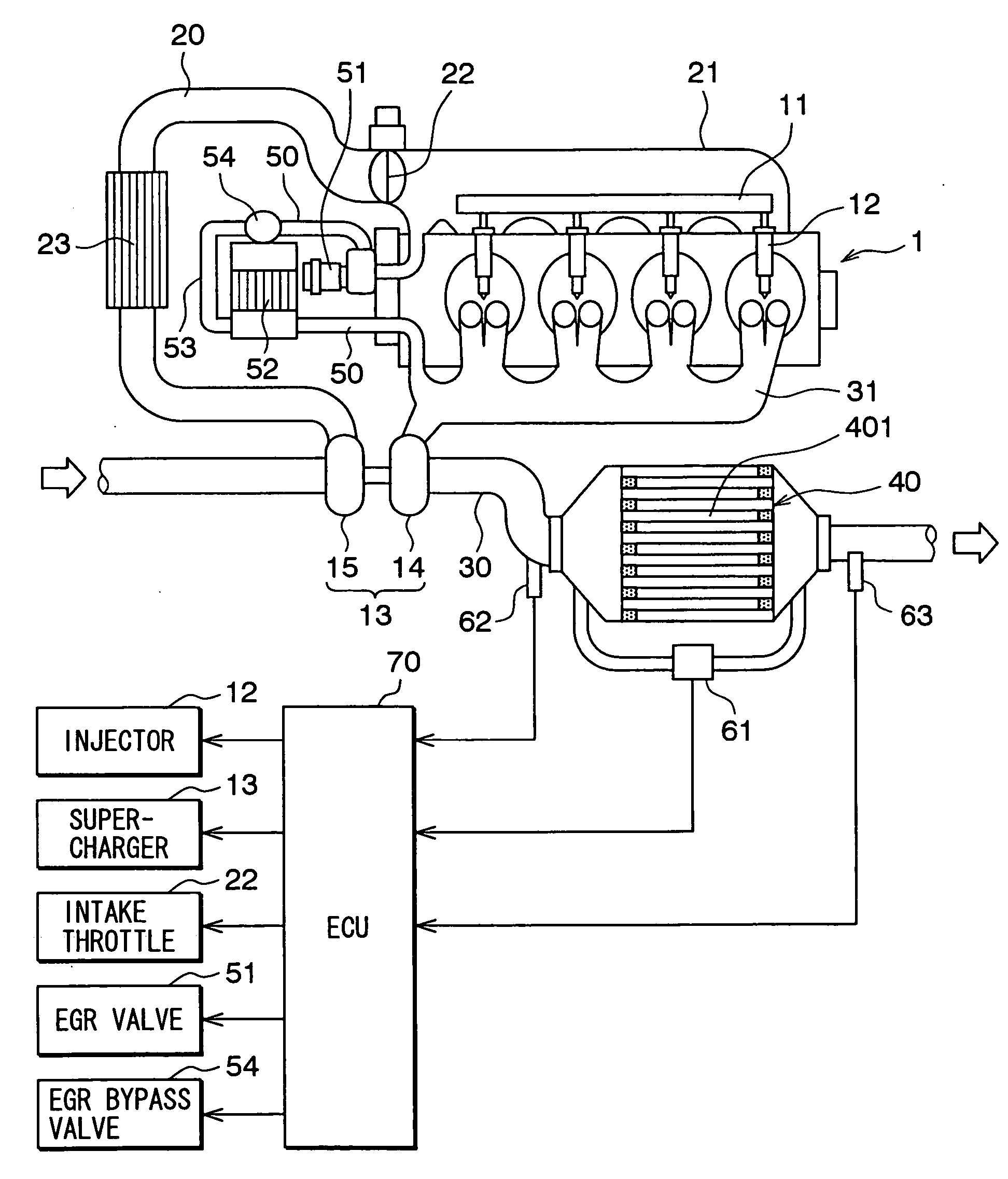
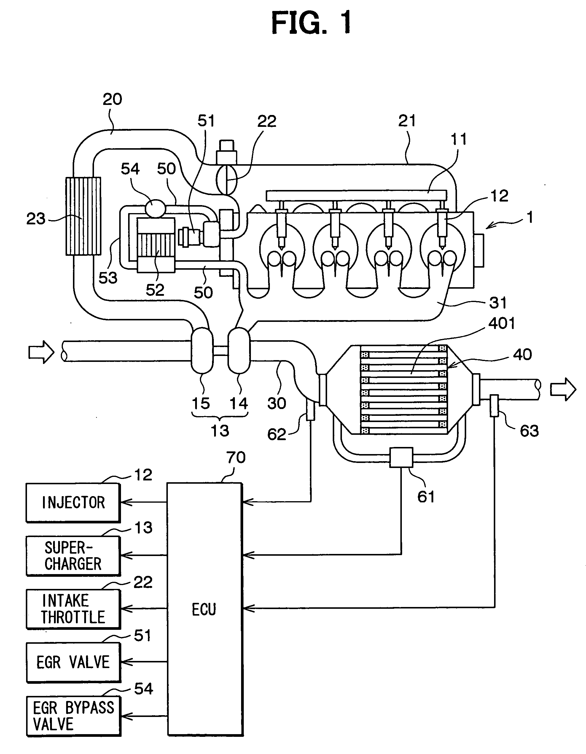
[0025] In the following is described an exhaust emission controls system according to a first embodiment of the present invention. FIG. 1 depicts an entire construction of an internal combustion engine (hereinafter referred to just as engine) 1 that is provided with the exhaust emission control system according to the first embodiment.

[0026] The engine 1 is a water-cooled diesel internal combustion engine that is mounted on a vehicle to drive the vehicle. The engine 1 includes a common rail 11 that accumulates high-pressure fuel therein, and a plurality of fuel injection valves 12 that are connected to the common rail 11 and inject the high-pressure fuel into cylinders of the engine 1. The engine 1 drives a pump (not shown) to pressurize a fuel into the high-pressure fuel and to pressure-supply the high-pressure fuel to the common rail 11. The common rail 11 and the fuel injection valve 12 form a fuel injection apparatus that is for injecting the fuel into the cylinders of the engi...

second embodiment

[0059] In the first embodiment, the ECU 70 determines that the front end portion of the particulate filter 40 is clogged in the step S101 in FIG. 5 when the front end PM accumulation amount becomes equal to or larger than the front end clogging determination threshold value. In the second embodiment, the ECU 70 determines that the front end portion of the particulate filter 40 is clogged in another way.

[0060]FIG. 10 depicts an estimated PM accumulation amount that is accumulated in the particulate filter 40 in a non-generation time when neither the normal regeneration nor the front end portion regeneration is performed. In the drawing, a solid line indicates a first estimated PM accumulation amount, which is the PM accumulation amount in the particulate filter 40 that is estimated from the pressure difference detected by the pressure difference sensor 61 between the front portion and rear portion of the particulate filter 40. A broken line indicates a second estimated PM accumulati...

third embodiment

[0066] In the second embodiment, the ECU 70 determines that the front end portion of the particulate filter 40 is clogged based on the first estimated PM accumulation amount in the non-regeneration time and the second estimated PM accumulation amount. In the third embodiment, the ECU 70 determines whether the front end portion of the particulate filter 40 is clogged or not based on the first estimated PM accumulation amount in the normal regeneration time and the second estimated PM accumulation amount.

[0067]FIG. 11 depicts an estimated PM accumulation amount that is accumulated in the particulate filter 40 when the normal generation time is performed. In the drawing, a solid line indicates the first estimated PM accumulation amount, and a broken line indicates the second estimated PM accumulation amount.

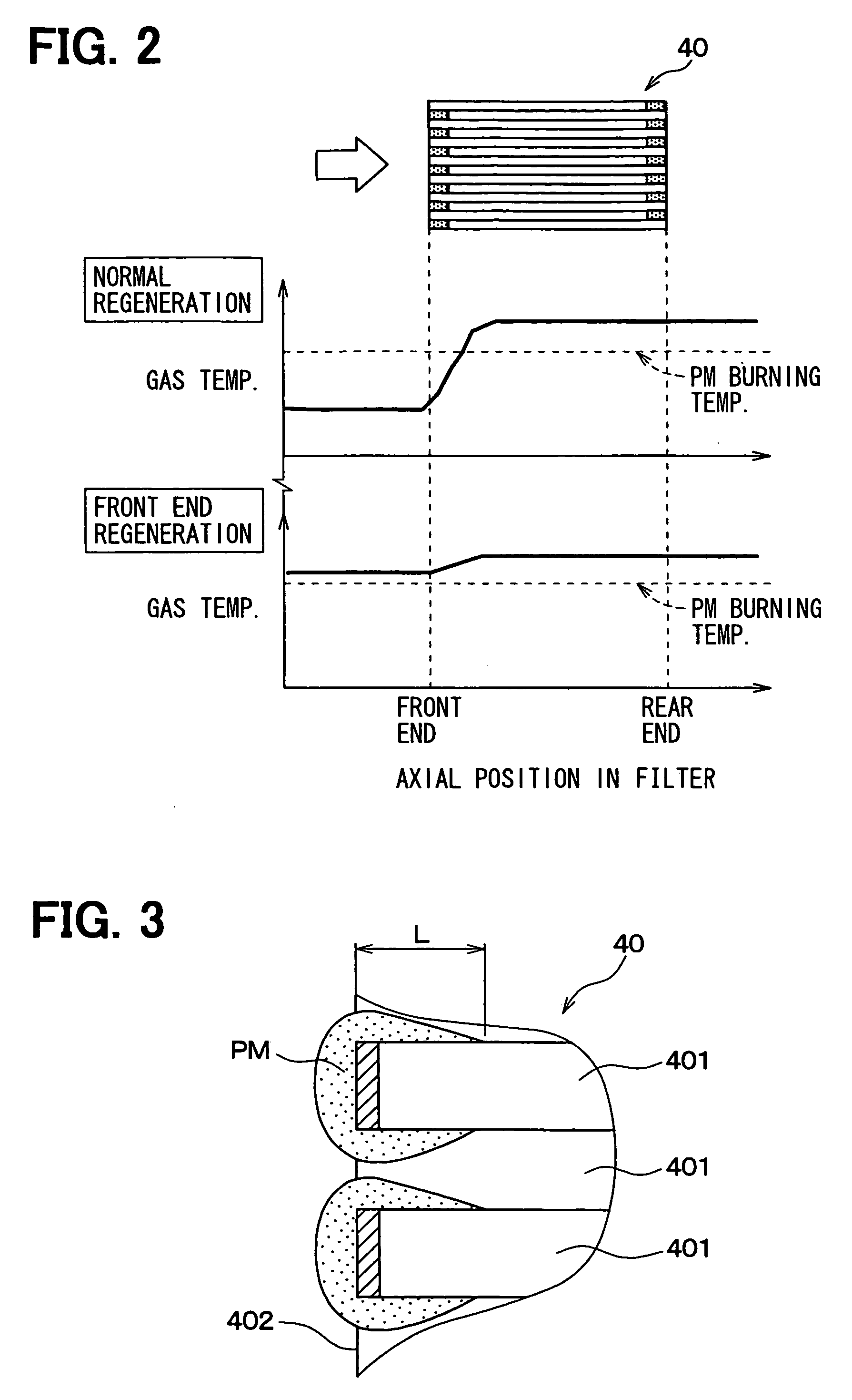
[0068] In the normal regeneration time of the particulate filter 40, the exhaust gas temperature is relatively low in the front end portion of the particulate filter 40. Thus, eve...


PUM


Abstract

In an exhaust emission control system for a vehicular internal combustion engine, a particulate filter collects particulate matters in an exhaust gas of the internal combustion engine. A filter regenerator regenerates the particulate filter by burning the particulate matters accumulated in the particulate filter. A filter front clogging detector determines whether a front end portion of the particulate filter is clogged by the particulate matters. A filter regeneration controller that controls the filter regenerator to perform a front regeneration to remove the particulate matters accumulated in the front end portion of the particulate filter when the filter front clogging detector determines that the front end portion of the particulate filter is clogged.

Description

CROSS REFERENCE TO RELATED APPLICATION [0001] This application is based upon and claims the benefit of priority of Japanese Patent Application No. 2005-203018 filed on Jul. 12, 2005, the content of which is incorporated herein by reference. FIELD OF THE INVENTION [0002] The present invention relates to an exhaust emission control system for an internal combustion engine provided with a particulate filter for removing particulate matters contained in an exhaust gas of the engine, and, more particularly, the system that can regenerate the particulate filter. BACKGROUND OF THE INVENTION [0003] In recent diesel internal combustion engines mounted on vehicles, a particulate filter is installed on a way of an exhaust pipe to collect particulate matters so as to reduce the particulate matters contained in an exhaust gas. [0004] The particulate filter is generally made of porous ceramics having a multiplicity of exhaust gas passages. When the exhaust gas passes through porous filter walls t...

Claims


Application Information

Patent Timeline
Patent Type & Authority Applications(United States)
IPC IPC(8): F01N3/00F01N3/02
CPCF01N3/023Y02T10/47F01N9/005F01N9/007F01N11/002F02B29/0406F02B37/00F02D41/0055F02D41/0245F02D41/029F02D41/405F02D2200/0812F02M25/0707F02M25/0728F01N9/002F02M26/05F02M26/25Y02T10/40
Inventor YAHATA, SHIGETOTOCHIKAWA, KAZUHARUKUBOSHIMA, TSUKASA
Owner DENSO CORP
Why Eureka
Try Eureka