RFID tag

a radio frequency identification and tag technology, applied in the field of rfid (radio frequency identification) tags, can solve the problem of insufficient elimination effect of illegal use, and achieve the effect of higher radiation and receiving characteristics of antennas and higher

Inactive Publication Date: 2006-09-21
FUJITSU LTD
View PDF5 Cites 11 Cited by
  • Summary
  • Abstract
  • Description
  • Claims
  • Application Information

AI Technical Summary

Benefits of technology

[0021] Considering the background explained above, an object of the present invention is to provide an RFID tag which ensures a higher effect for avoiding illegal use and can obtain higher radiation and receiving characteristics of antenna.

Problems solved by technology

However, the related art, as explained above has a problem in that since a part of the tag is broken when the RFID is peeled and the broken area is apparent, a motive or a chance to repair the broken area will be given to a person who is trying to illegally use the tag and thereby the effect for eliminating illegal use becomes insufficient.

Method used


Image

  • RFID tag
  • RFID tag
  • RFID tag

Examples


first embodiment

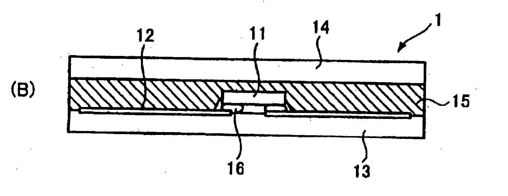
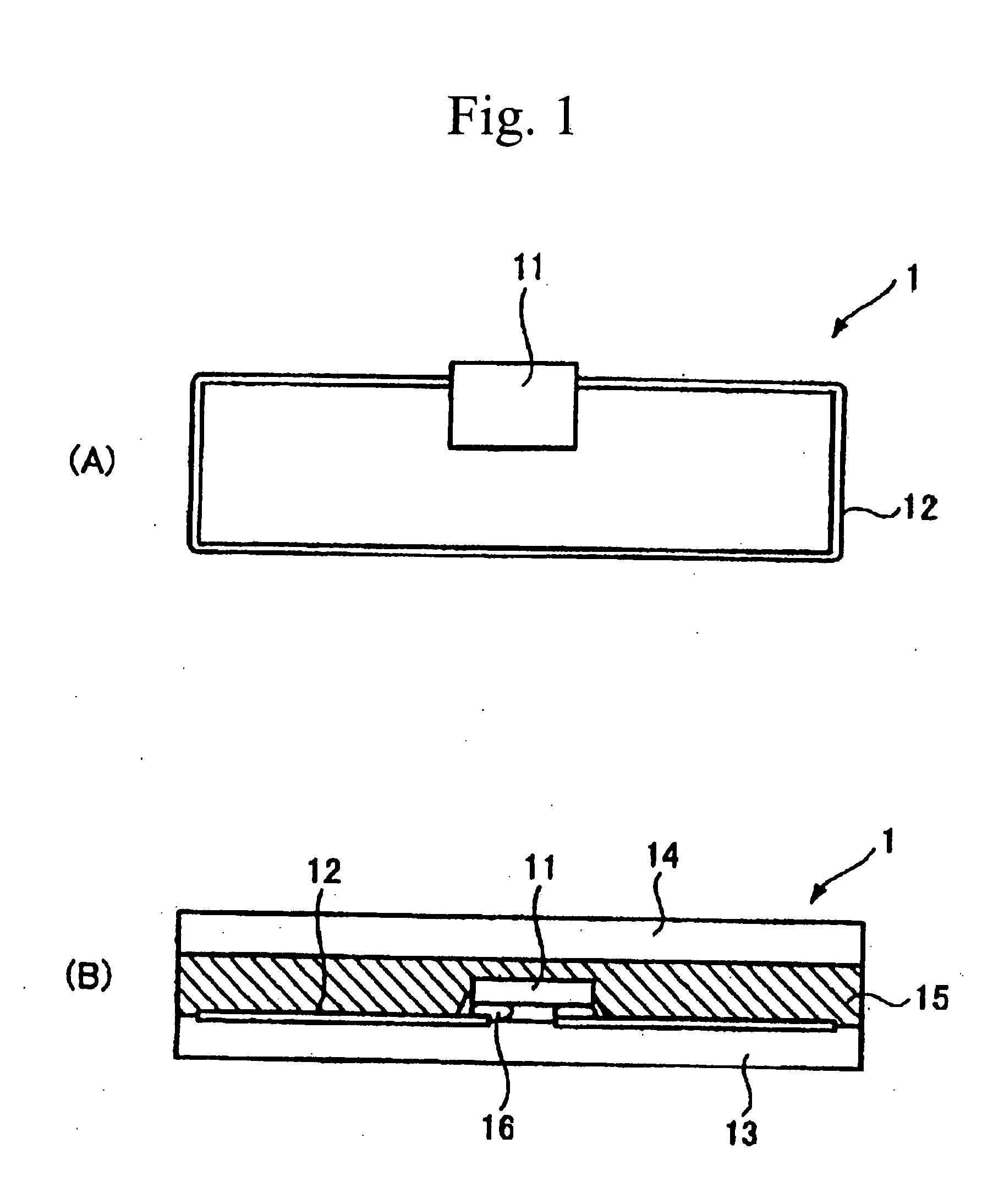
[0045]FIG. 4 illustrates a structure of the RFID tag of the present invention. In this RFID tag, the operating frequency is assumed as about 950 MHz but another frequency may also be selected. The size of this RFID tag is set to 120 mm×60 mm.

[0046] In the RFID tag, an antenna 18 is formed on a film sheet 3 and a detecting block 4 is formed in the circumference of the antenna 18.

[0047] Moreover, an IC chip 17 is arranged in the manner as bridging over the antenna 18 and a detecting block 4. The film sheet is formed of a dielectric material substrate such as FR-4 and so or PET (abbreviation of Polyethylene Telephthalate). The detecting block 4 is formed of a single loop in a length of about 29 cm. The RF tag forms a loop as the detecting block 4 in the circumference of the antenna 18 on the film sheet 3 as illustrated in FIG. 4. Moreover, the antenna 18 and IC chip 17 and so on are covered with a cover sheet (not illustrated). Actually, the RF tag is bonded to an item at the film she...

second embodiment

[0057] Next, FIG. 7 illustrates the antenna impedance (A) when the detecting block of the RF tag in the present invention exists and the antenna impedance (B) when the detecting block does not exist. FIG. 7 illustrates the antenna impedances plotted on a Smith chart.

[0058]FIG. 7(A) illustrates the impedance when the detecting block 41 of FIG. 6 exists. In this case, the antenna impedance is assumed as Z2. In this RF tag, the impedance Z of IC chip 17 in FIG. 6 becomes equal to 36−j245[Ω]. The antenna impedance Z2 becomes equal to 47+j269Ω. When Z2 is normalized to 50Ω, Z2=47 / 50+j269 / 50=0.94+j5.38Ω is obtained. When Z is normalized to 50Ω, Z=36−j245=0.72−j4.9Ω is obtained. The normalized impedances Z, Z2 are plotted on the Smith chart as illustrated in FIG. 7(A). The operating frequency is set to about 950 MHz. The Smith chart FIG. 7(A) shows that Z and Z2 are almost in a conjugate relationship and these are almost matched.

[0059]FIG. 7(B) can be obtained by plotting the antenna impe...

third embodiment

[0063]FIG. 9 illustrates a radiation spectrum of the antenna showing the RF tag in the present invention. [a.u.] used here is used as a relative unit and is an abbreviation of arbitrary unit. In FIG. 9, field intensity E [a.u.] is plotted on the vertical axis, while frequency is plotted on the horizontal axis. FIG. 9 shows the curve when the detecting block is not provided, namely the double-loop is not provided and the curve when the detecting block 7 is provided, namely the double-loop is provided. In the case where the double-loop is provided (the loops where single-line loop is respectively provided in the internal side and external side), a resonance point (1) of the loop can be found. Moreover, the maximum radiation of the antenna in the RF tag can be found as (2). If the loop length of the detecting block 7 is set to an integer multiple of the half wavelength, the resonance point (1) of the loop will happen to be matched with the maximum radiation (2).

[0064] However, such an ...


PUM


Abstract

With the RFID comprising a transmitting and receiving antenna, a detecting block formed in the circumference of the antenna, and an electronic component connected to the antenna and detecting block to detect breakdown of the detecting block, illegal use can be prevented, matching between the tag antenna and IC chip can also be attained with inclusion of the detecting means, and higher radiation and receiving characteristics of antenna can also be obtained without deterioration of antenna gain. Moreover, the RFID is very effective for keeping security because illegal use of the RFID tag through re-adhesion thereof to an item can be prevented.

Description

BACKGROUND OF THE INVENTION [0001] 1. Field of the Invention [0002] The present invention relates to an RFID (Radio Frequency Identification) tag. The “RFID tag” used in the present specification is also called an “Inlay for RFID tag” because it is also used as an internal structural member (inlay) for an “RFID tag”. Otherwise, the “RFID tag” is also called a “radio IC tag”. Moreover, this “RFID tag” includes a non-contact type IC card. [0003] 2. Description of the Related Art [0004] In recent years, an external device represented by a reader / writer and various RFID tags for exchanging information using radio waves on a non-contact basis have been proposed. As a kind of such RFID tags, a tag having a structure such that an antenna pattern for radio wave communication and an IC chip are mounted on a base sheet formed of plastic or paper has also been proposed. The RFID tag of the type explained above is considered to be used in such a mode that such a tag is attached to items and the...

Claims


Application Information

Patent Timeline
Patent Type & Authority Applications(United States)
IPC IPC(8): G06K19/06
CPCG06K19/07372G06K19/07749G06K19/0775H01L2224/16H01L2924/3011H01L2924/01087H01L2224/16227H01L2224/16225G06K19/07
Inventor YAMAGAJO, TAKASHIMANIWA, TORUKAI, MANABUBABA, SHUNJINAKANISHI, YUICHI
Owner FUJITSU LTD
Why Eureka
Try Eureka