Variable grip structure

a grip structure and variable technology, applied in the field of grip structure, can solve the problems of limited satisfaction of the gripping person, left room for further development, index finger and middle finger feeling unpleasant,

Inactive Publication Date: 2006-03-02
PENTEL KK +1
View PDF2 Cites 20 Cited by
  • Summary
  • Abstract
  • Description
  • Claims
  • Application Information

AI Technical Summary

Benefits of technology

[0008] The present invention essentially permits an elastic member and a shaft body which fixes the elastic member to be rotatable relative to each other and provides means for keep

Problems solved by technology

However, since a grip portion of an elastic member is usually fixed to the shaft cylinder, there is a limit to the satisfaction of the gripping person on account of the size of the gripping hand and his or her personal preference.
However, as this would require an impression material and a mold, it would be expensive and, moreover, not only the molding work is troublesome but also the writing tool, though g

Method used


Image

  • Variable grip structure
  • Variable grip structure
  • Variable grip structure

Examples


Embodiment Construction

[0058] Modes for carrying out the invention will be illustrated, and will be described in detail with reference to the drawings.

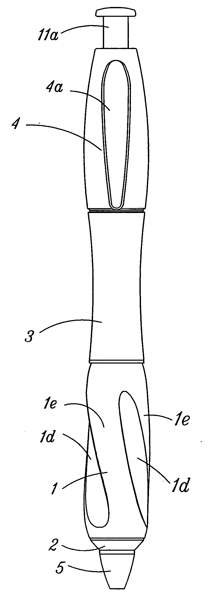
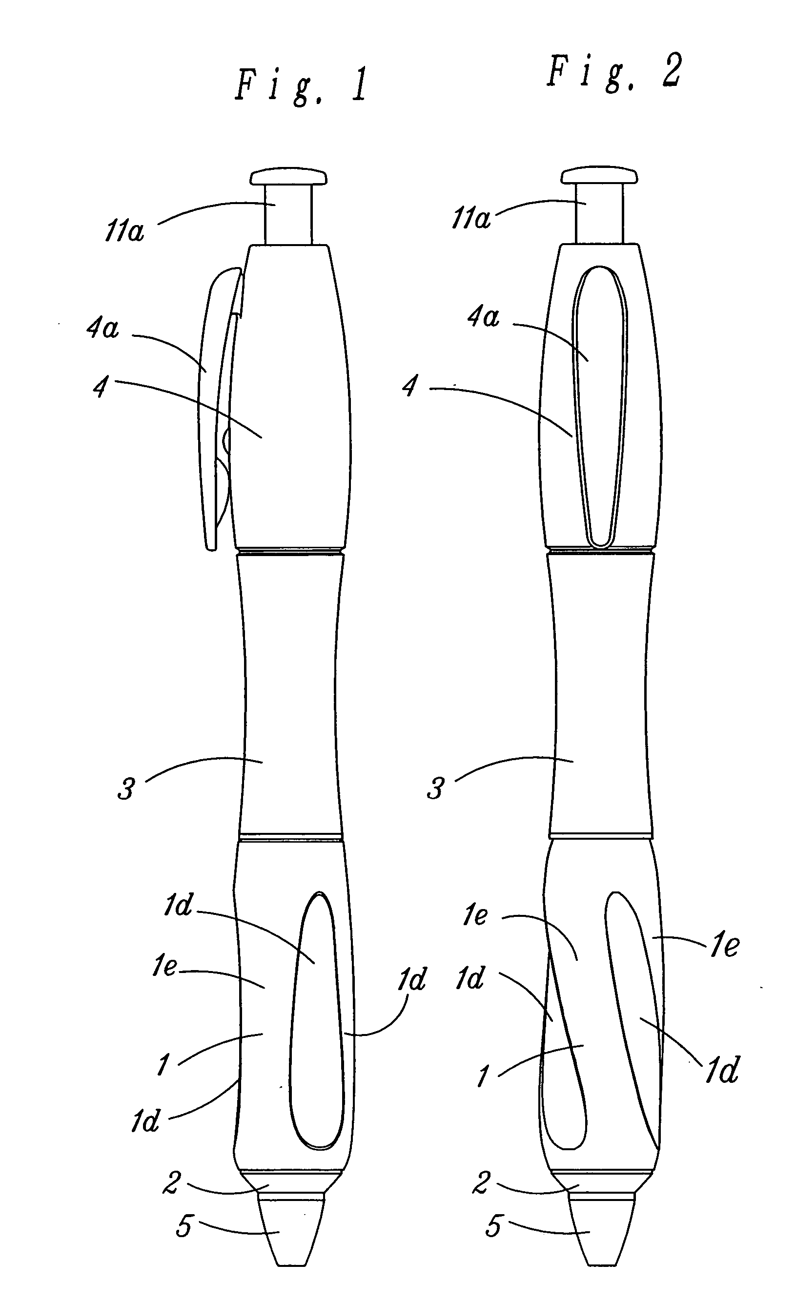
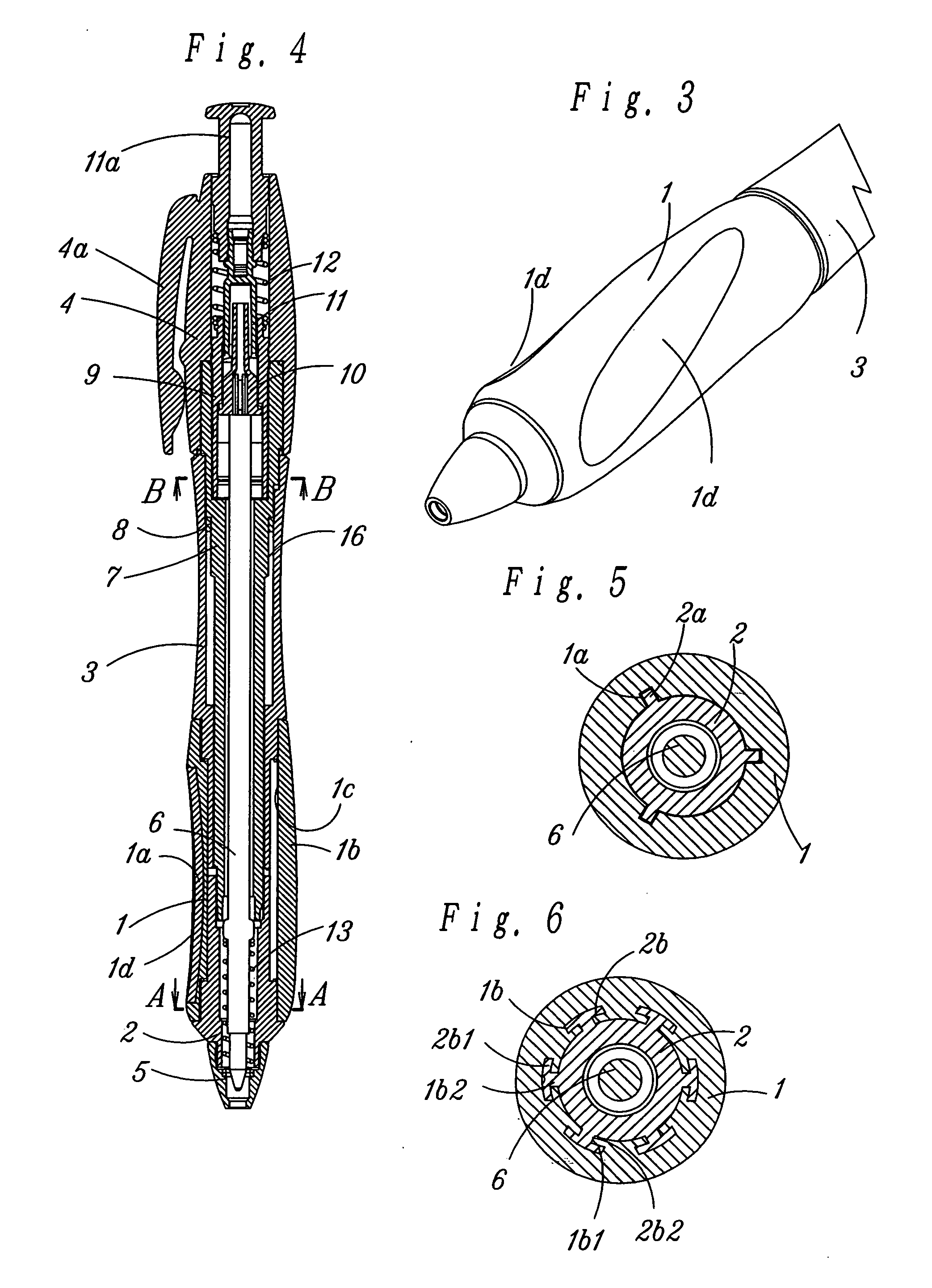
[0059] A first embodiment of the invention will be described with reference to FIG. 1 through FIG. 4. FIG. 1 is an external view showing a case that there is no rotation of an elastic member relative to a shaft body. Reference numeral 1 denotes a grip portion made of a soft elastic member, and the grip portion 1 has a hollow portion 1c. The forward end side (the lower side in the drawing) of the grip portion 1 is unrotatably fixed to a forward shaft (forward member) 2. On the other hand, the rear end side (the upper side in the drawing) of the grip portion 1 is also unrotatably fixed to a middle shaft (rear member) 3. Its rear shaft 4, though unrotatably fixed to the forward shaft 2 via a linking member 7, is rotatably arranged relative to the middle shaft 3. Therefore, when the middle shaft 3 and rear shaft 4 are held with fingers or the like and rotated ...


PUM


Abstract

A relatively rotational engagement is made between an elastic member and a shaft body to which the elastic member is fixed, and means for keeping their relative rotating actions is provided. This configuration makes it possible the adaptation of the shape to the hand size and preference of each of users, which may individually vary from one user to the other, by the relative rotation of those shaft body and elastic member and also makes it possible to keep that shape. There is an additional advantage of allowing an appropriate degree of hardness to be selected and maintained. Moreover, these can be achieved by a relatively simple component configuration.

Description

TECHNICAL FIELD [0001] The present invention relates to a grip structure having a grip portion consisting of an elastic member. Examples of those having such a grip include writing tools such as mechanical pencils, ball-point pens and whiteout (eraser) pens, cutting tools such as snap-off blade knives, chisels and screw drivers, input pens for use in personal digital assistants (PDAs) and electronic notebooks, and bicycle handle bars. BACKGROUND ART [0002] Attempts have been made in pursuit of better gripping performance of such grip structures as those mentioned above. One example of them is a research and development project involving contrivances regarding the hardness, surface state and shape of the grip portion. [0003] However, since a grip portion of an elastic member is usually fixed to the shaft cylinder, there is a limit to the satisfaction of the gripping person on account of the size of the gripping hand and his or her personal preference. [0004] In order to solve this pr...

Claims


Application Information

Patent Timeline
IPC IPC(8): A46B5/02B43K23/008B25G1/00B43K3/00B43K24/08B62K21/26
CPCB25G1/00B43K24/084B43K23/008B43K3/00
Inventor FUKUI, HISAOSENER, JAMESCOSTELLO, KEVINJMATHIEU, DAVE
Owner PENTEL KK
Why Eureka
Try Eureka