Turbine Blade for a Turbine

a turbine blade and turbine blade technology, applied in the direction of machines/engines, liquid fuel engines, lighting and heating apparatus, etc., can solve the problems of increasing the scrap rate in most cases, the production of the passage, the production of the chamber and the outlet line is comparatively expensive, etc., and achieves the effect of simple and cost-effectiv

Inactive Publication Date: 2009-03-26
SIEMENS AG
View PDF11 Cites 26 Cited by
  • Summary
  • Abstract
  • Description
  • Claims
  • Application Information

AI Technical Summary

Benefits of technology

[0007]The object of the present invention is therefore the provision of a generic-type turbine blade which is to be produced in a particularly simple and cost-effective manner.

Problems solved by technology

A disadvantage in the case of the turbine blade which is known from the prior art relates to the production of the passages, of the chamber and of the outlet line if the turbine blade and its cavities are produced in the casting process.
These cavities are to be produced comparatively expensively by means of mostly complex casting cores.
For this purpose, a complexly structured casting core and / or casting shell corresponding to the desired cavity structure is required, which, however, are to be positioned securely and accurately in the casting device cost-intensively and only in a time-consuming manner so that when casting turbine blades with such complex structures an increased scrap rate ensues in most cases.
If on the other hand the cavities which are provided in the blade wall are produced by means of different coatings, then the masking of the uncoated rough components which is required for it is an especially time-consuming working step which leads to a prolonged and expensive production.

Method used


Image

  • Turbine Blade for a Turbine
  • Turbine Blade for a Turbine
  • Turbine Blade for a Turbine

Examples


Embodiment Construction

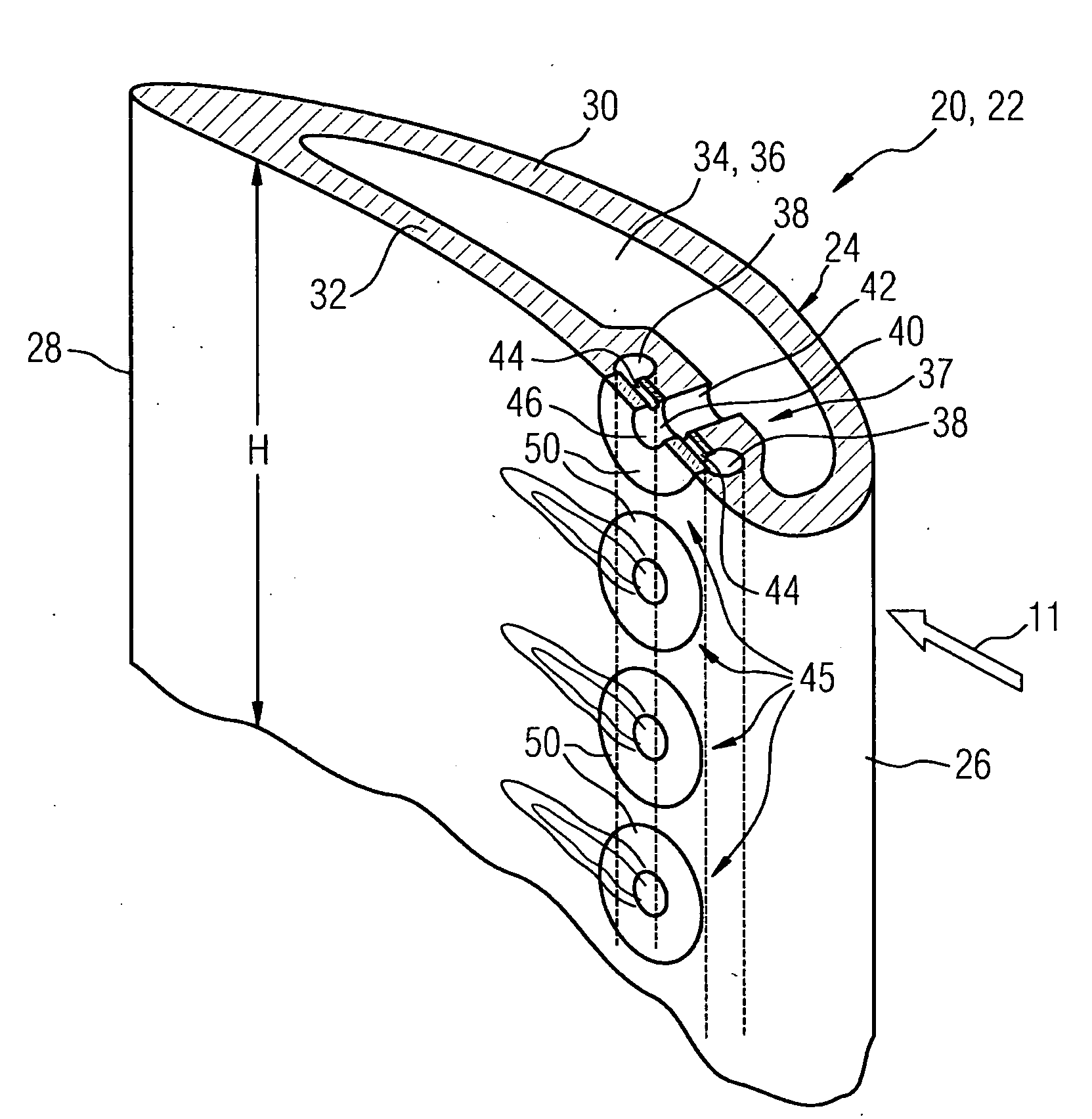
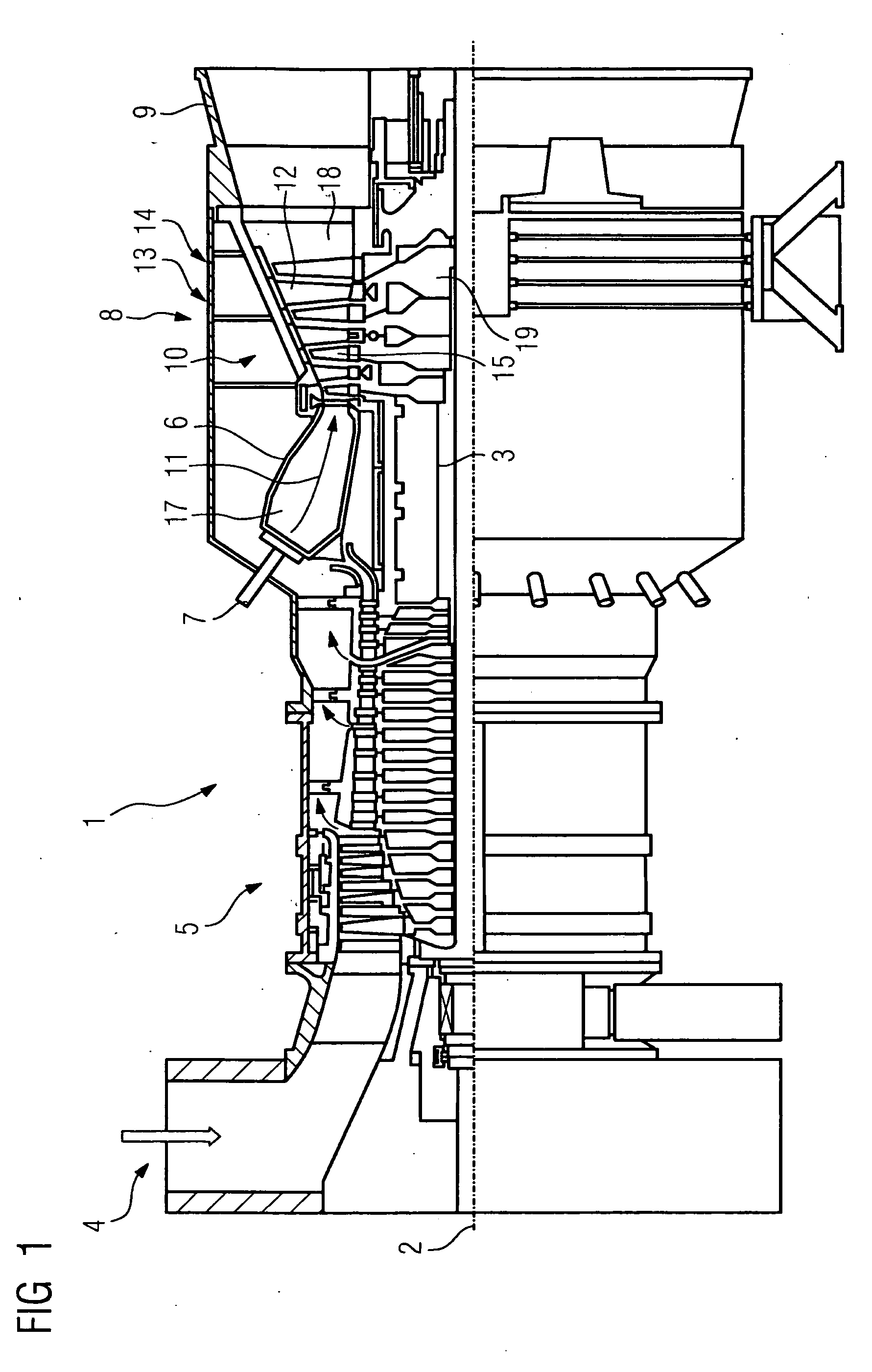
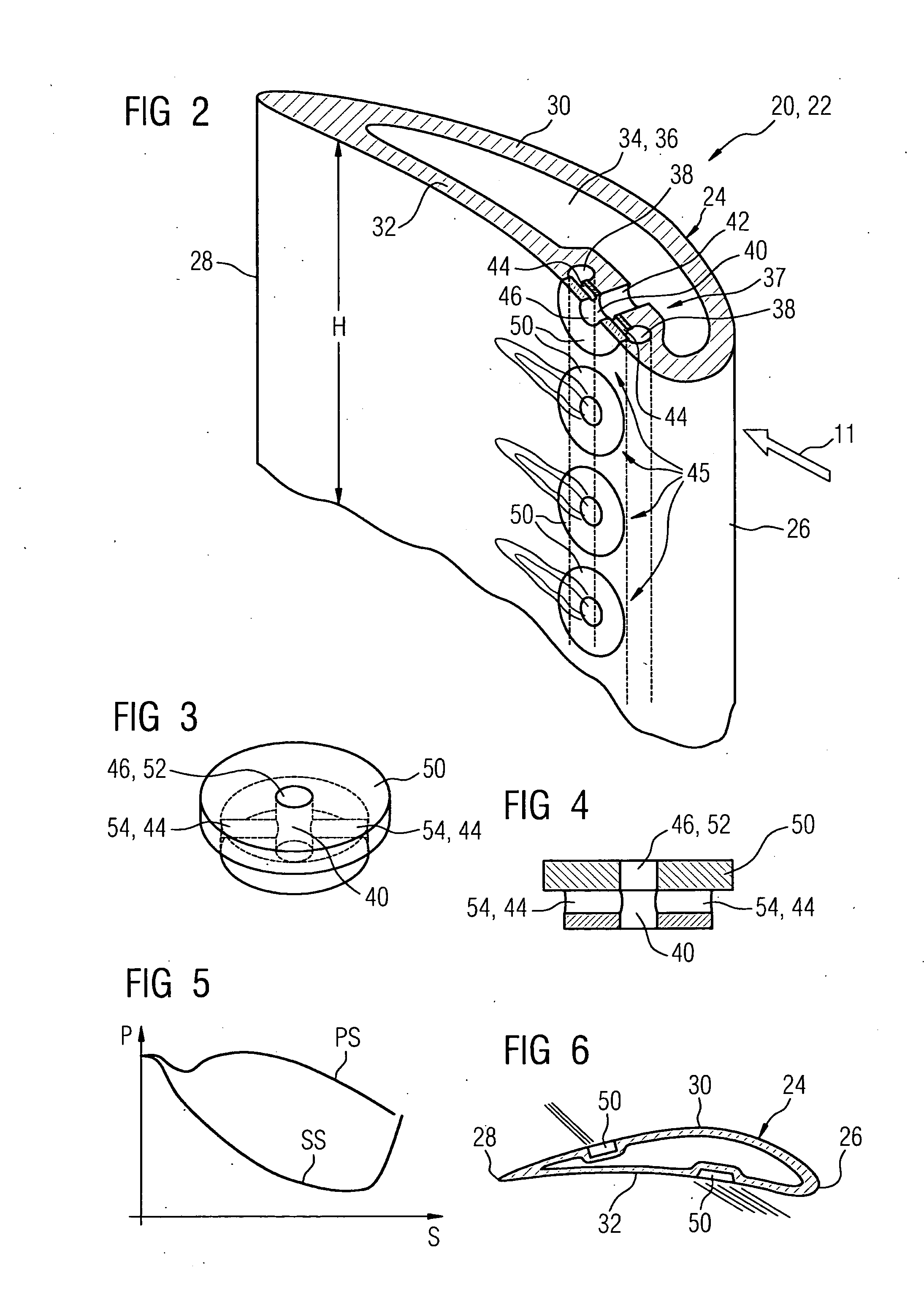
[0042]FIG. 1 shows a gas turbine 1 in a longitudinal partial section. Inside, it has a rotor 3 which is rotatably mounted around a rotational axis 2 and which is also referred to as a turbine rotor. An intake duct 4, a compressor 5, a toroidal annular combustion chamber 6 with a plurality of burners 7 which are arranged rotationally symmetrically to each other, a turbine unit 8 and an exhaust gas duct 9, follow each other along the rotor 3. The annular combustion chamber 6 forms a combustion space 17 which communicates with an annular hot gas space 18. Four turbine stages 10 which are connected in series form the turbine unit 8 there. Each turbine stage 10 is formed from two blade rings. In the hot gas space 18, a row 14 which is formed from rotor blades 15 follows a stator blade row 13 in each case, as seen in the flow direction of a hot gas 11 which is produced in the annular combustion chamber 6. The stator blades 12 are fastened on the stator, whereas the rotor blades 15 of a ro...


PUM


Abstract

The invention relates to a blade for a turbine comprising a blade wall, a first channel for guiding a first medium and a second channel for guiding a second medium that can be supplied to the turbine blade separately from the first medium. In order to combine both media, which are supplied separately, into one mixture, a turbine blade has least one chamber which is arranged in the interior or in the blade wall and said chamber is connected to said channels via a respective connection line. In order to provide a particularly simple component that is economical to produce, the chamber and/or the outlet conduit are a least partially delimited and/or formed by an insert accommodated in the wall.

Description

CROSS REFERENCE TO RELATED APPLICATIONS[0001]This application is the US National Stage of International Application No. PCT / EP2007 / 052235, filed Mar. 9, 2007 and claims the benefit thereof. The International Application claims the benefits of European application No. 06008321.9, filed Apr. 21, 2006, both of the applications are incorporated by reference herein in their entirety.FIELD OF THE INVENTION[0002]The invention relates to a turbine blade for a turbine, with a blade wall and with a first passage for guiding a first medium and a second passage for guiding a second medium which can be fed to the turbine blade separately from the first medium, wherein for mixing the two separately feedable media to form a mixture the turbine blade has at least one chamber which is arranged on the inside or in the blade wall and is connected to the two passages via a connecting line in each case.BACKGROUND OF THE INVENTION[0003]Such a turbine blade is known for example from WO 2005 / 003517 A1. The...

Claims


Application Information

Patent Timeline
Patent Type & Authority Applications(United States)
IPC IPC(8): F01D5/18
CPCF01D5/18F01D9/065F02C3/16F23R3/286F02K3/10F23C2900/07001F23R3/14F02K3/08
Inventor BEECK, ALEXANDER R.HOFFMANN, STEFAN
Owner SIEMENS AG
Why Eureka
Try Eureka