Eureka AIR delivers breakthrough ideas for toughest innovation challenges, trusted by R&D personnel around the world.

Encoding and decoding using constrained interleaving

a technology of constrained interleaving and encoder, which is applied in the direction of coding, code conversion, instruments, etc., can solve the problems of too difficult to handle joint consideration of both the minimum distance and the interleaver design, and achieve the effect of reducing the total number of allowable interleaver combinations, reducing the interleaver gain, and reducing the measur

Inactive Publication Date: 2015-02-05
TRELLIS PHASE COMM LP
View PDF16 Cites 25 Cited by
  • Summary
  • Abstract
  • Description
  • Claims
  • Application Information

AI Technical Summary

Benefits of technology

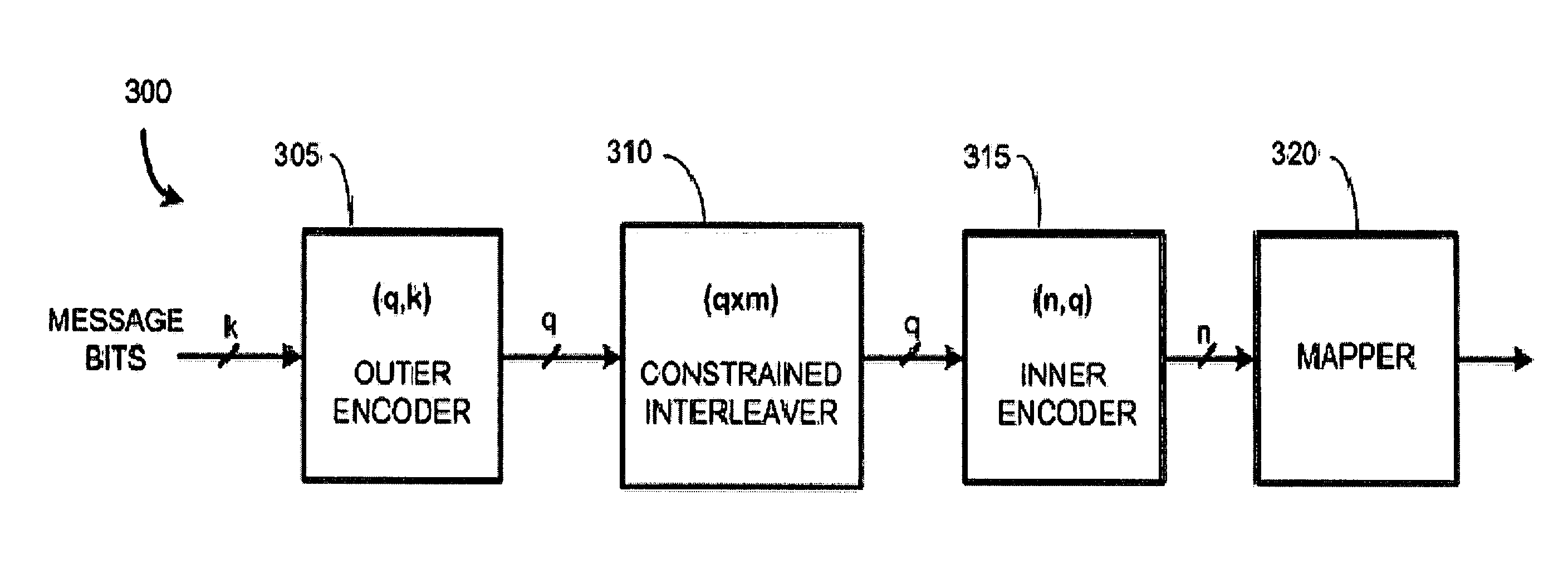
The present invention provides a family of encoders, decoders, transmitters, receivers, and methods, apparatus and systems employing the same. An interleaver is selected to improve the bit error rate performance of a serial concatenated code. This allows for the use of shorter interleasers and the construction of new types of serial concatenated codes that would not have their performance benefits if prior art uniform interleaving was applied. Additional constraints can be added to force dsc>d0di, but these constraints lower the total number of allowable interleoter combinations and interleaver gain. Numerical simulations can be used to determine if the additional constraints would improve the overall coding gain for a given application.

Problems solved by technology

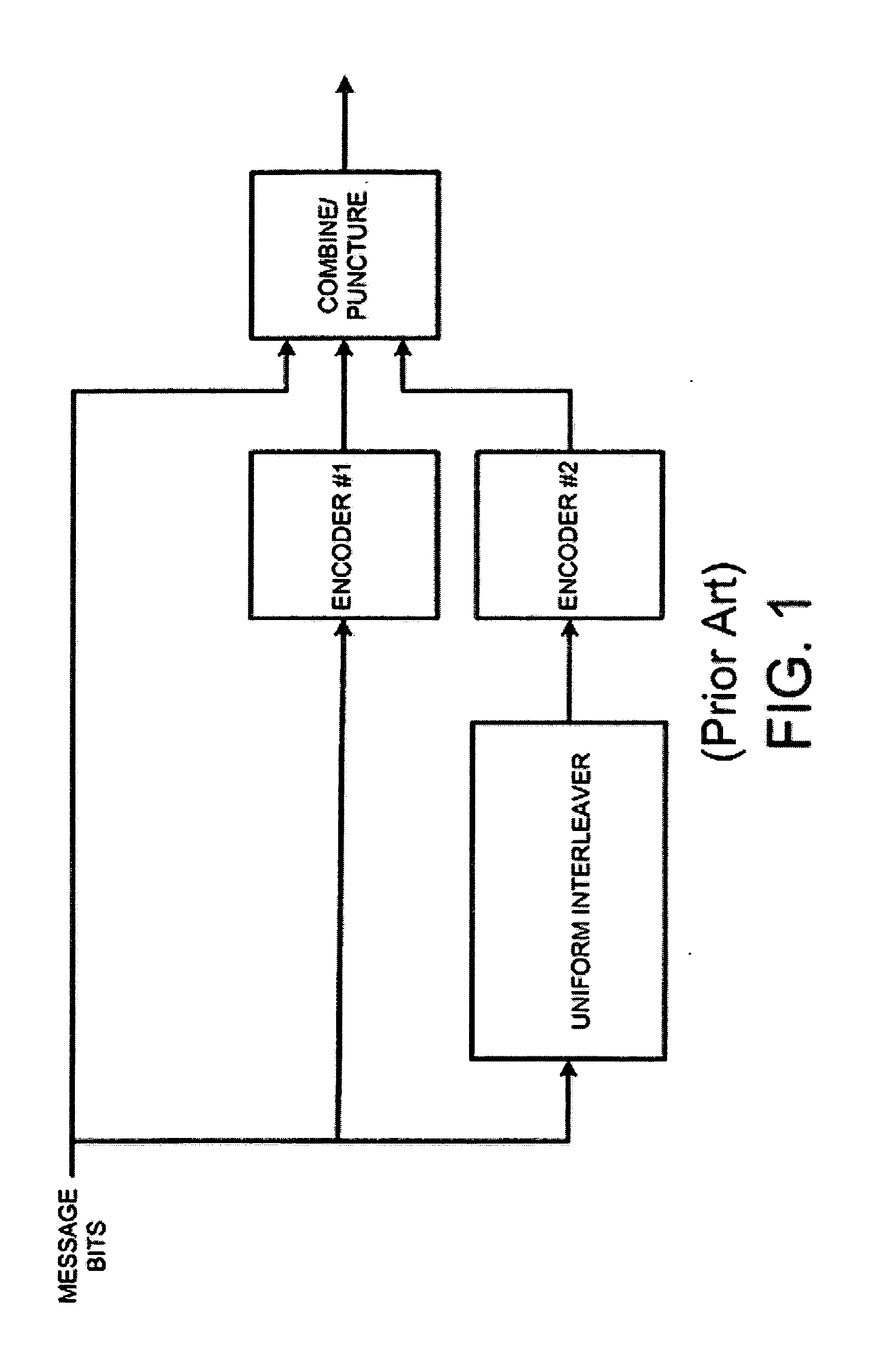
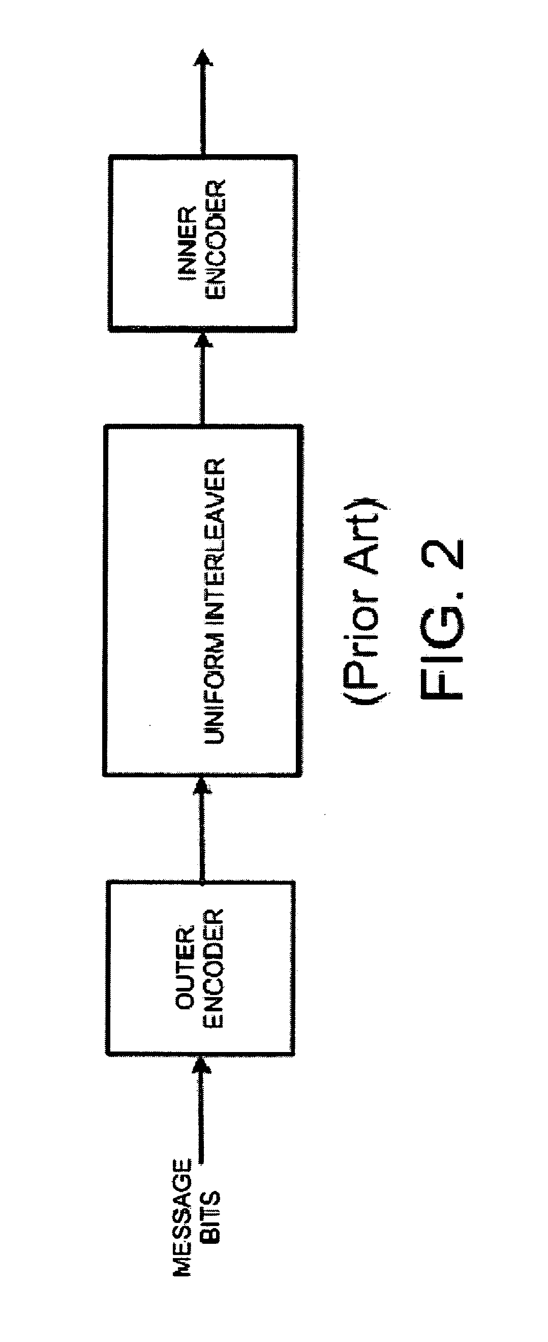
While it would be desirable to consider the minimum distance of the overall code for short to moderate interleaver sizes, it is conventional wisdom that the joint consideration of both the minimum distance and the interleaver design is too difficult to handle [6].

Method used


Image

  • Encoding and decoding using constrained interleaving
  • Encoding and decoding using constrained interleaving
  • Encoding and decoding using constrained interleaving

Examples


Embodiment Construction

[0045]In this patent application, various forms of serial concatenation are considered. For example, when two block codes are serially concatenated, this is referred to as SC-BC (serially concatenated block codes). When the inner code is a convolutional code, this is referred to as SCCC (serial concatenation with a convolutional code). The acronym IRCC is also used, and this stands for inner recursive convolutional code. An IRCC is a recursive convolutional code that is used as an inner code in a concatenated encoder. When the inner code is specifically a recursive convolutional code, i.e., when an IRCC is used in a serial concatenated code, this is referred to SC-IRCC (serial concatenation with an inner recursive convolutional code). As it turns out, the constrained interleavers designed for these various types of serially concatenated codes preferably require different sets of constraints to achieve the best performance. Hence the encoder and decoder designs for these various code...


PUM


Abstract

Serially-concatenated codes are formed in accordance with the present invention using a constrained interleaver. The constrained interleaver cause the minimum distance of the serial concatenated code to increase above the minimum distance of the inner code alone by adding a constraint that forces some or all of the distance of the outer code onto the serially-concatenated code. This allows the serially-concatenated code to be jointly optimized in terms of both minimum distance and error coefficient to provide significant performance advantages. These performance advantages allow a noise margin target to be achieved using simpler component codes and a much shorter interleaver than was needed when using prior art codes such as Turbo codes. Decoders are also provided. Both encoding and decoding complexity can be lowered, and interleavers can be made much shorter, thereby shortening the block lengths needed in receiver elements such as equalizers and other decision-directed loops. Also, other advantages are provided such as the elimination of a error floor present in prior art serially-concatenated codes. That allows the present invention to achieve much higher performance at lower error rates such as are needed in optical communication systems.

Description

[0001]This patent application is a continuation of co-pending U.S. patent application Ser. No. 12 / 926,539 filed Nov. 11, 2010, which claims priority to U.S. provisional patent application No. 61 / 344,675, entitled “Encoding and decoding using constrained interleaving,” filed Sep. 10, 2010.BACKGROUND OF THE INVENTION[0002]1. Field of the Invention[0003]This invention relates generally to communication encoders, decoders, transmitters, receivers, and systems. More particularly, aspects of the invention relate a family of encoders and a family of decoders that make use of constrained interleaving with various forms of serially concatenated codes.[0004]2. Description of the Related Art[0005]Various forms of concatenated codes are known in the art. Turbo codes are widely used and represent parallel concatenated codes. In the literature, interleaver design has been discussed with both parallel and serial concatenation but mainly in connection with parallel concatenated codes. For example, ...

Claims


Application Information

Patent Timeline
IPC IPC(8): G06F11/10
CPCG06F11/10G06F11/1048H03M13/271H03M13/2742H03M13/29H03M13/2906H03M13/2933H03M13/2939H03M13/2972H03M13/3746H03M13/4115H03M13/6362
Inventor FONSEKA, JOHN P.DOWLING, ERIC MORGAN
Owner TRELLIS PHASE COMM LP
Why Eureka
Eureka Blog
Learn More