Inclination measurement instrument

Inactive Publication Date: 2006-03-09
SATORU YOSHIGOU
View PDF43 Cites 12 Cited by
  • Summary
  • Abstract
  • Description
  • Claims
  • Application Information

AI Technical Summary

Benefits of technology

[0019] (5) The reference arm is provided with a protrusion formed on a portion to be in contact with a face to be measured on an outer side of the main body frame. The protrusion is attached to an intersection point of the face to be measured such as a pillar and a corner of a sill or the like, and the reference arm is tilted supported by the corner to which the protrusion is attached as a fulcrum, thereby making the measurement easy. When the telescoping

Problems solved by technology

However, when measuring a vertical inclination, the pendulum has to be prepared as described above, which makes it difficult to measure a horizontal inclination and a vertical inclination alternately.
Furthermore, when moving the inclinometer, the pendulum could hit against something damaging it or the pendulum itself.
In addition, if a leveling line by which the pendulum is hung touches

Method used


Image

  • Inclination measurement instrument
  • Inclination measurement instrument
  • Inclination measurement instrument

Examples


Embodiment Construction

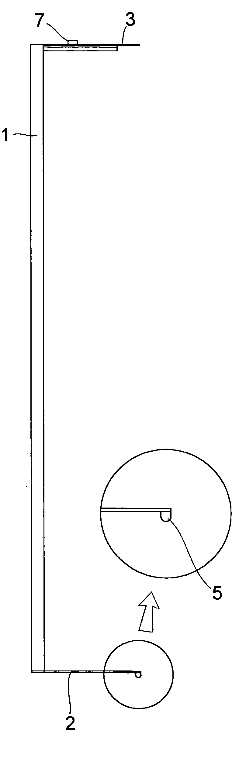
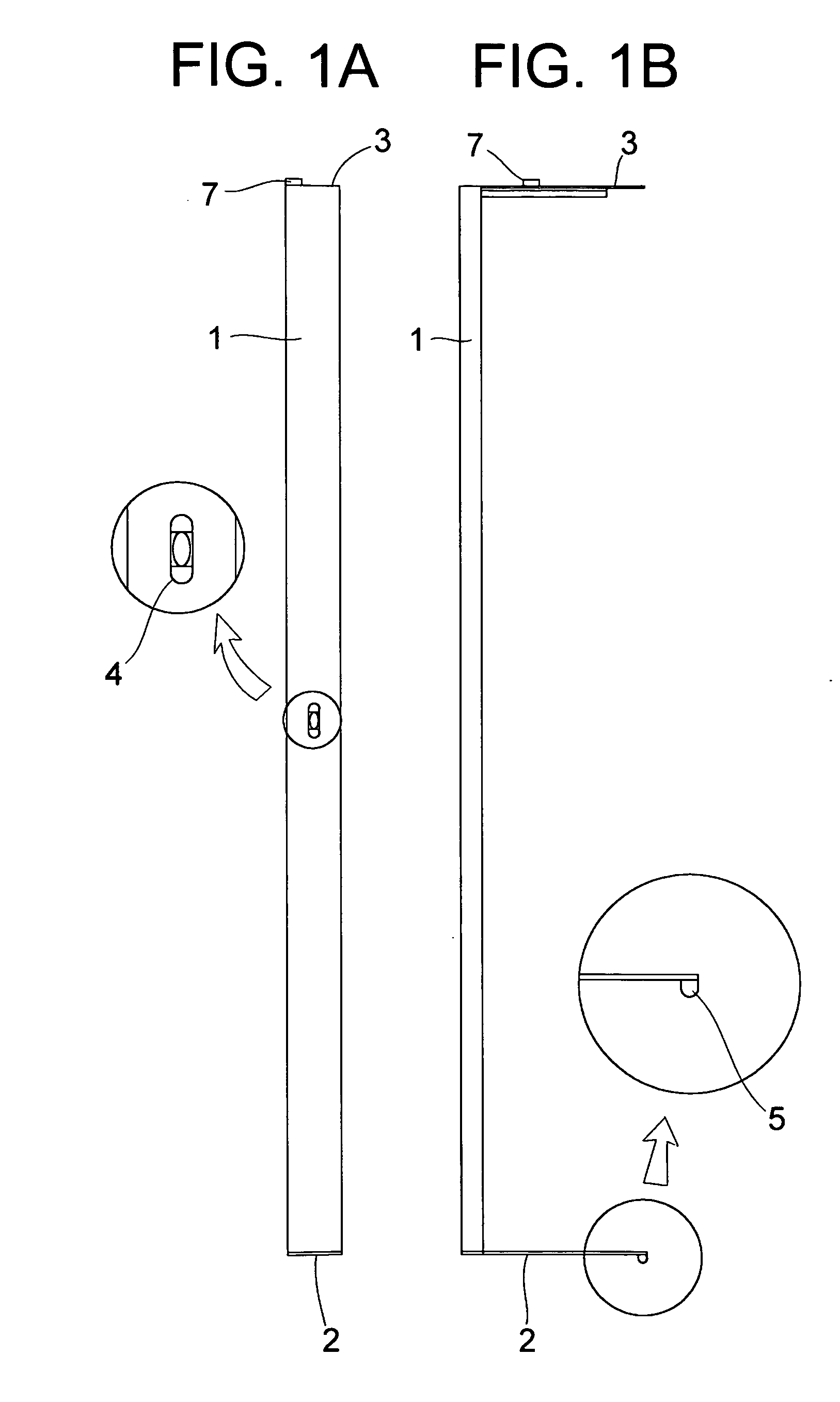
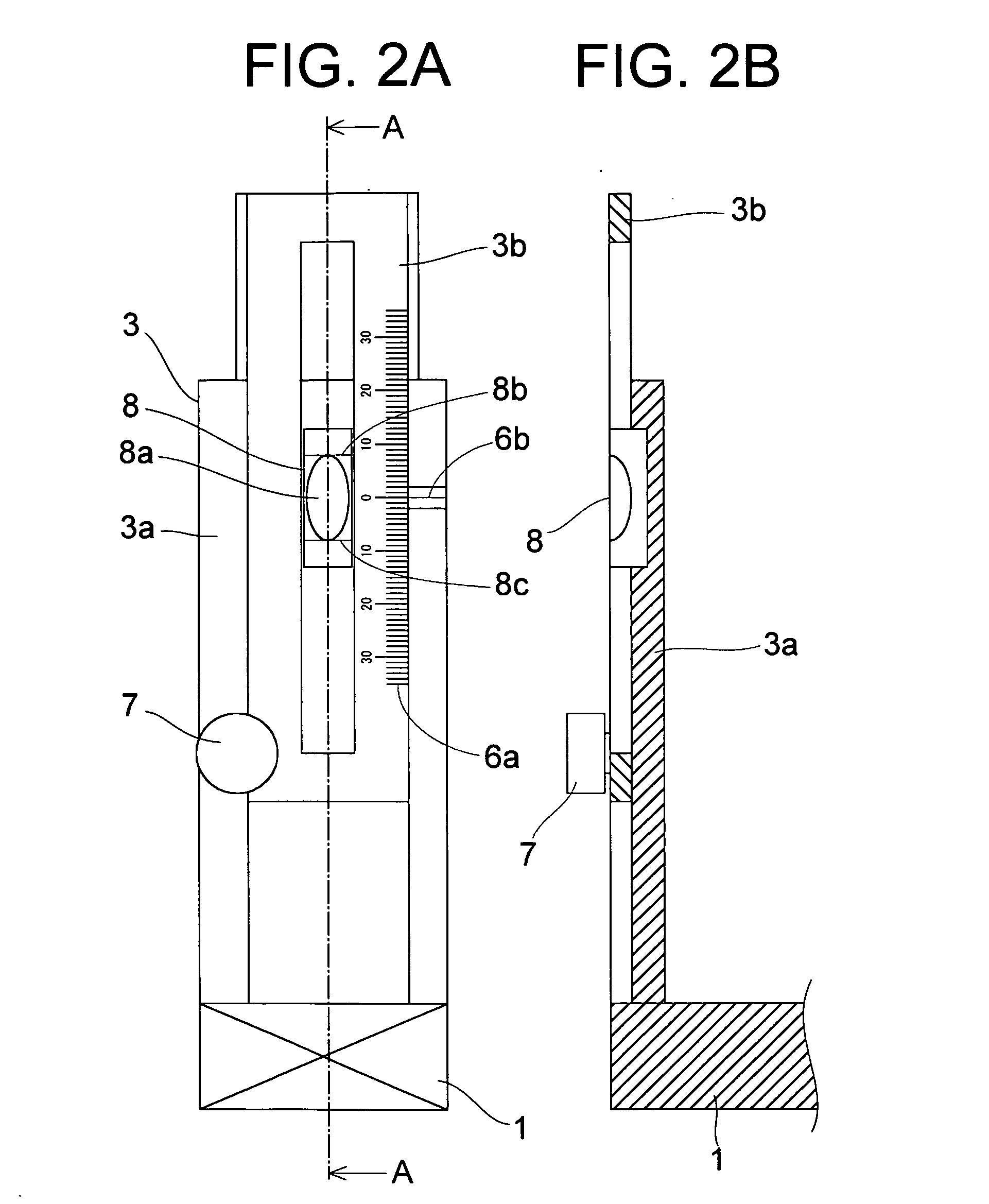
[0030]FIGS. 1A and 1B are drawings illustrating an inclination measurement instrument according to an embodiment of the present invention as a whole, wherein FIG. 1A is a front view and FIG. 1B is a right side view. FIGS. 2A and 2B are drawings illustrating a telescoping arm in FIGS. 1A and 1B in detail, wherein FIG. 2A is a plan view of FIG. 1A and FIG. 2B is a sectional view taken along the line A-A in FIG. 2A.

[0031] In FIGS. 1A and 1B, an inclination measurement instrument in the present embodiment comprises a pillar-shaped main body frame 1 having a length of 1000 mm with a reference arm 2 and a telescoping arm 3 that are formed at both ends of the main body frame 1 so as to be perpendicular to the main body frame 1 and oriented in the same direction. The main body frame 1 is provided with a bubble gauge 4 for determining a level of the main body frame 1 at a center thereof. The reference arm 2 has a predetermined length, and a protrusion 5 having a round surface extending towa...


PUM


Abstract

An inclination measurement instrument formed by removing a pendulum and a circular dial from an inclinometer main body, which is less likely to cause a measurement error and capable of measuring an inclination of an object to be measured in a short time. The inclination measurement instrument has a main body frame (1) that is to be arranged along a face (H) to be measured, a reference arm (2) and a telescoping arm (3) that are brought into contact with the face (H) to be measured. The reference arm (2) and the telescoping arm (3) are formed at both ends of the main boy frame (1) so as to be perpendicular to the main body frame and oriented in the same direction. The telescoping arm (3) has a slide scale movable by telescoping the telescoping arm (3) and a bubble gauge for determining a level of the telescoping arm. The telescoping arm (3) is telescoped with the tip ends of the reference arm (2) and the telescoping arm (3) in contact with the face (H) to be measured, and the level of the telescoping arm (3) is adjusted based on the bubble gauge of the telescoping arm, and then the inclination of the face (H) to be measured can be measured by the slide scale.

Description

TECHNICAL FIELD [0001] This invention relates to an inclination measurement instrument for measuring an inclination of pillars, floors, work pieces, or the like. BACKGROUND ART [0002] In a method of measuring a degree of inclination of pillars or floors of buildings, or the like, a level vial or a plumb bob is used in general. With a level vial, a degree of inclination is confirmed by an air bubble. A plumb bob determines a degree of inclination by a value measured with a scale. Currently, as inclinometers for measuring an inclination value per 1 meter, known are a plumb bob inclinometer (trade name: Vertical Inclinometer V2) described in “Vertical Inclinometer V2”, [online], Kabushiki Kaisha Asia Consultant, [searched on Oct. 15, 2002], Internet <URL: http: / / www.asia-ct.com / research / kei.htm>(referred to as “Non-Patent Document No. 1” hereinafter) and a circular dial inclinometer (trade name: Dial Plumb Bob VH) described in “Dial Plumb Bob VH”, [online], Ozaki Mfg. Co., Ltd., ...

Claims


Application Information

Patent Timeline
IPC IPC(8): G01C9/00G01C9/24G01C9/26
CPCG01C9/26
Inventor KISHIKAWA, TAKEHIKO
Owner SATORU YOSHIGOU
Why Eureka
Try Eureka