Engine control device of contruction machinery

Inactive Publication Date: 2006-03-09
KOBELCO CONSTR MASCH CO LTD
View PDF13 Cites 6 Cited by
  • Summary
  • Abstract
  • Description
  • Claims
  • Application Information

AI Technical Summary

Benefits of technology

[0019] Thus, a load on the engine and the like due to the restart of the engine a

Problems solved by technology

As a result, the engine is automatically stopped while keeping a low-temperature state in a non warm-up machine, and after that, a restarting operation of the engine puts a heavy load on the engine and peripheral devices such as a water pump and a cell motor (hereinafter referred to as engine and the like), which is likely to cause a failure.
Further, since the restarting operation of the engine must be performed, a heavy load is put on an operator's operation.
It is noted that although only canceling an automatic stop control before warming up the machin

Method used


Image

  • Engine control device of contruction machinery
  • Engine control device of contruction machinery
  • Engine control device of contruction machinery

Examples


first embodiment (see figs.1 and 2)

First Embodiment (see FIGS. 1 and 2)

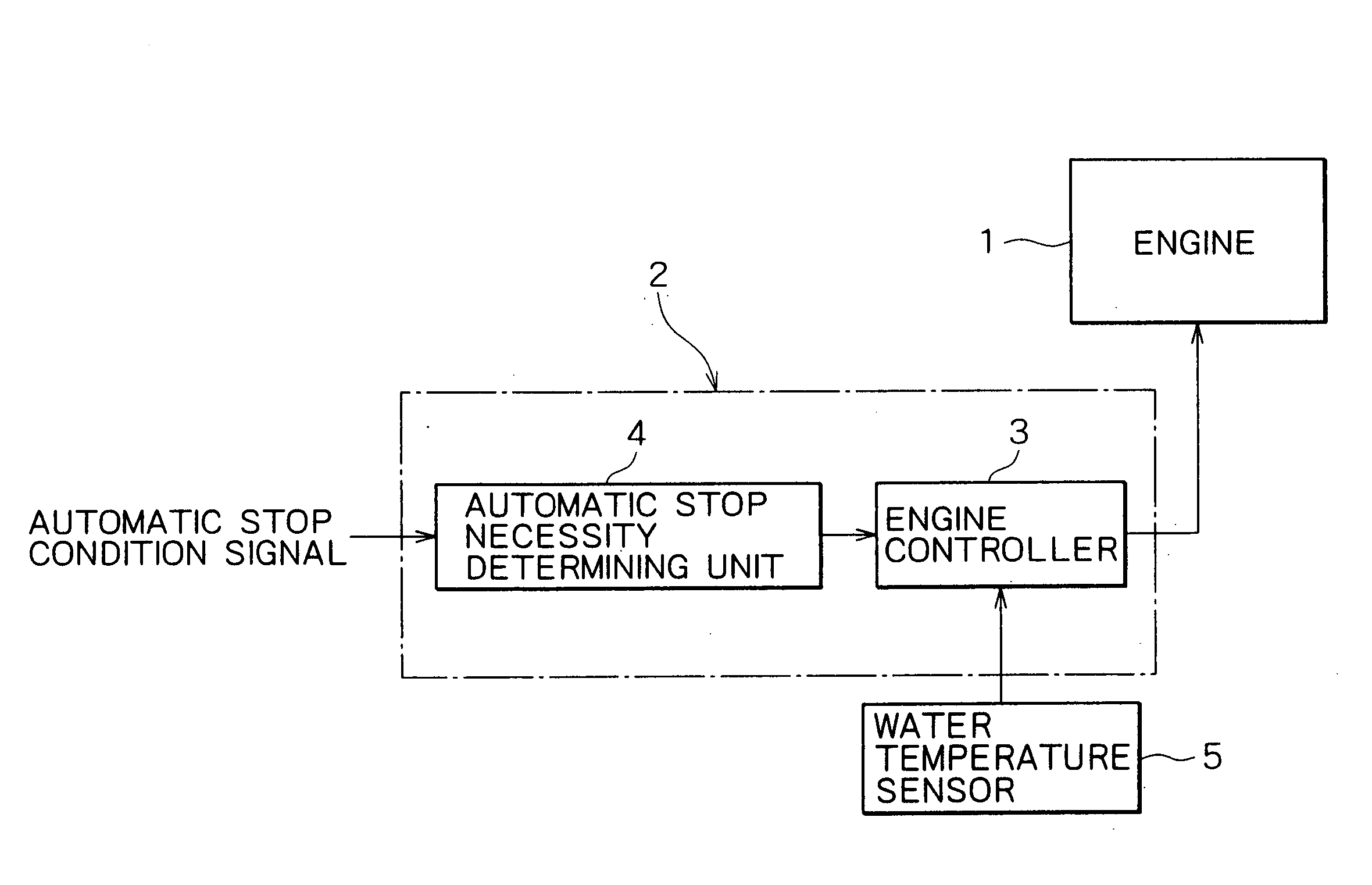
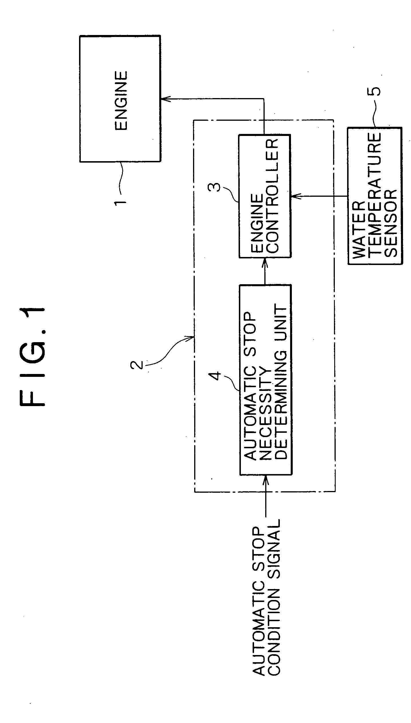
[0028] An engine 1 as a power source is controlled by a controller 2 as control means.

[0029] The controller 2 includes an engine controller 3 for sending a signal of a stop command to the engine 1 (particularly engine governor controller) and an automatic stop necessity determining unit 4 for determining whether or not it is necessary to perform an automatic stop control as a previous stage.

[0030] To this automatic stop necessity determining unit 4 is input a signal relating to a predetermined automatic stop condition. Necessity of the automatic stop control is determined based on this automatic stop condition signal.

[0031] It is noted that the automatic stop condition is, for example, any one or both of the following conditions: [0032] 1) a gate lever for opening and closing a gateway of a cabin is opened; [0033] 2) an operating lever as operation means for operating a work actuator is in non-operation.

[0034] The automatic stop condition is d...

second embodiment (see figs.3 and 4)

Second Embodiment (see FIGS. 3 and 4)

[0043] Only different points from the first embodiment will be described in the following embodiments.

[0044] When the engine 1 is stopped while keeping a high temperature state, troubles such as seizing of a turbine shaft can be generated.

[0045] Thus, in the second embodiment, a cool-down operation of reducing (cooling) a temperature of the engine 1 is automatically performed as required before the automatic stop control is started. In this case, a period of the cool-down operation is automatically selected among two types in accordance with a detected temperature and is counted by a timer 6 provided in the engine controller 3.

[0046] Namely, in a flow chart of FIG. 4, when the automatic stop conditions are met (in a case of YES in Step S11), the detected water temperature A is compared with a predetermined reference temperature A1 in Step S12. If a requirement of A≧A1 is satisfied in Step S12, a set value B1 as a cool-down time B is selected i...

third embodiment (see fig.5)

Third Embodiment (see FIG. 5)

[0052] The third embodiment is configured as a modified embodiment from the second embodiment so that an engine is stopped after it is determined whether a cool-down operation is required or not and completion of the cool-down is detected.

[0053] Since the block configuration of the third embodiment is apparently the same as FIG. 1, a drawing is omitted while using FIG. 1.

[0054] Actions of the third embodiment will be described with reference to FIG. 5. After it is determined that the automatic stop conditions are met in Step S21, the detected water temperature A is compared with a cool-down starting temperature As1 predetermined as a temperature at which the cool-down operation should be started (Step S22).

[0055] In a case of NO, that is in a case of A1, since the cool-down operation is not required, an engine stop action is immediately performed in Step S23.

[0056] On the other hand, in a case where it is determined to be A≧As1 in Step S22 (in a case...


PUM


Abstract

An engine control device for a construction machine of the present invention is configured so that the engine control device comprises an engine as a power source, a controller for performing an automatic stop control to automatically stop the engine when a predetermined automatic stop condition is met, a water temperature sensor for detecting a cooling water temperature of the engine, and that after start-up of the engine, even if the automatic stop condition is met, the engine is not automatically stopped until the detected water temperature reaches a predetermined value or more to complete a warm-up operation. The engine control device is also configured so that before the engine is automatically stopped, a cool-down operation of the engine is performed as required and after the engine is stopped, the engine is restarted as required and the warm-up operation is performed.

Description

TECHNICAL FIELD [0001] The present invention relates to an engine control device for a construction machine in which an engine is automatically stopped (auto stop) in non-operation time. BACKGROUND ART [0002] A construction machine including an automatic stop function for automatically stopping an engine when predetermined automatic stop conditions (for example, a gate lever for opening and closing a gateway to a cabin is opened and a lever for operating a work actuator is in non-operation) is met has been disclosed in Japanese Patent Laid-Open Nos. 2000-96627 and 2001-41069. [0003] However, when the automatic stop conditions are met, an engine is automatically stopped only by the condition. Thus, when for example an operator leaves a machine for inspections or the like during a warm-up operation after start-up of the engine particularly in the cold time, the engine is automatically stopped in the middle of the warm-up operation. [0004] As a result, the engine is automatically stopp...

Claims


Application Information

Patent Timeline
IPC IPC(8): F02D45/00F02N17/00E02F9/20E02F9/22F02D17/00F02D29/00F02D29/02F02D41/06F02N11/08F02N15/00F02N99/00
CPCE02F9/2246E02F9/226F02D29/00F02N2200/023F02N11/0803F02N11/0829F02D41/068
Inventor UMEZU, YOSHIYASUKAMON, YOSHIKI
Owner KOBELCO CONSTR MASCH CO LTD
Why Eureka
Try Eureka